アプリケーション ソリューション RS485 通信回路設計 — VOOHU
RS-485 (EIA/TIA-485 規格) RS-485 バスは、長距離伝送、マルチノード ネットワーキング、および強力なコモンモード除去機能を備えており、産業オートメーション、データ収集、計装、ビル管理、およびその他の分野で広く使用されています。
VOOHU Electronics (VOOHU) は、RS-485 通信ノード向けに信頼性の高い物理層サポート コンポーネントを提供しており、顧客と協力して RS-485 インターフェイスのリファレンス回路とデバイス選択の推奨事項を提供し、システムの干渉防止機能と通信の信頼性を向上させることもできます。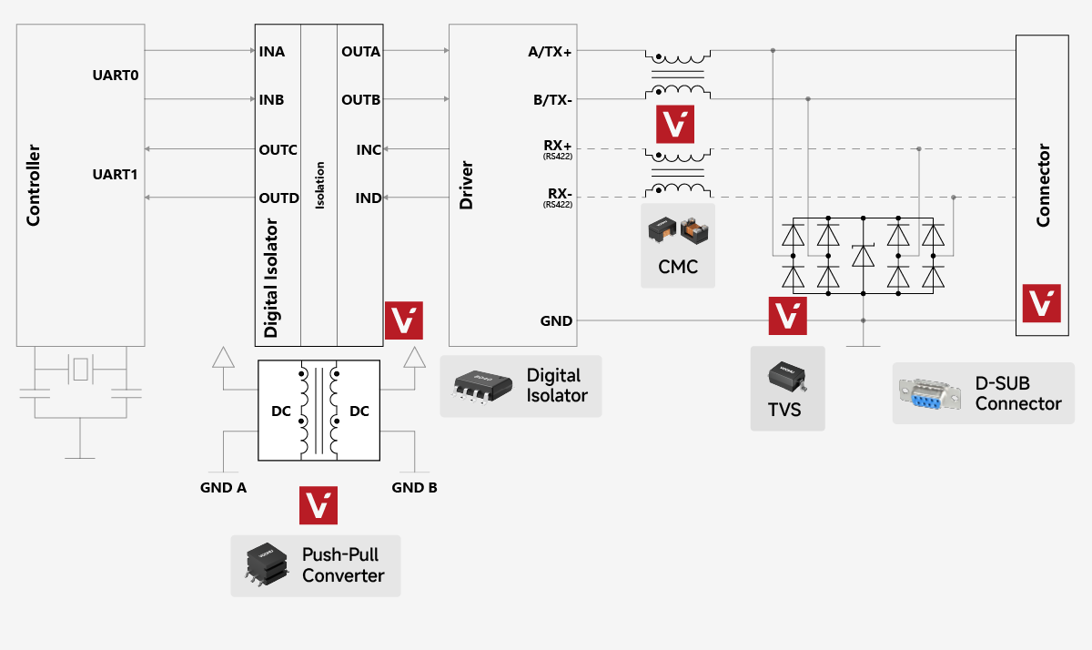
1. RS-485 トランシーバー
RS-485 トランシーバーは、MCU と RS-485 バス間の物理インターフェイスを実装するコア チップで、TTL/CMOS ロジック レベルと差動バス信号間の双方向変換を実行します。 MCU とバス間の電気インターフェイスを実装し、レベル変換と方向制御を完了し、バス障害保護を提供します。また、ノイズ耐性を強化し、コモンモード干渉を効果的に抑制し、-7V ~ +12V のコモンモード電圧範囲を備えています。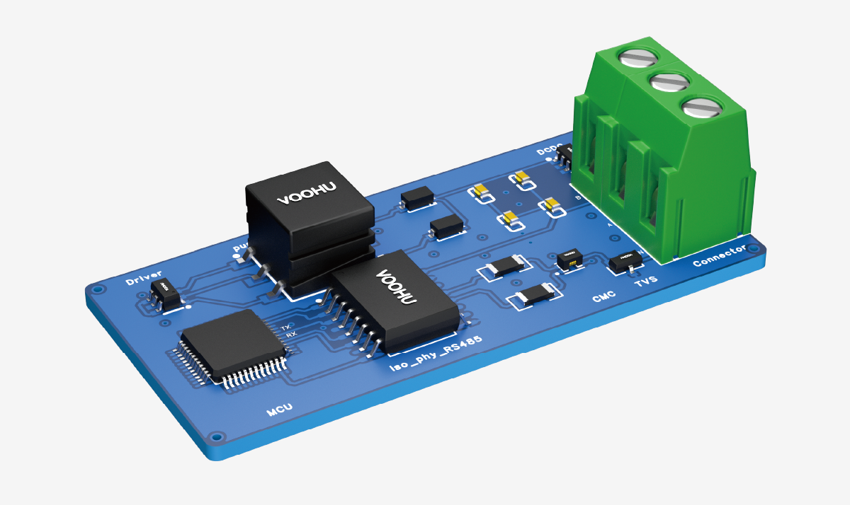
主な機能は次のとおりです。
-
レベル換算: コントローラーからのシングルエンド論理信号 (DI、RO) を送信用の差動バス信号 (A、B) に変換します。受信中に、差動バス信号を MCU が認識できるシングルエンドの論理レベルに変換します。
-
バスの運転: 差動ドライバーは、最大 1200 メートルの通信距離をサポートするのに十分な駆動能力を備えています。
-
送信方向制御: RS-485 は半二重モードで動作します。トランシーバーはイネーブル ピン (DE、RE#) を使用して送信状態と受信状態の切り替えを制御し、バス方向の管理を実現します。一般的な方法: 各 RS-485 デバイスは通常、受信モードにあり、送信するデータがある場合にのみ送信モードに切り替わります。
-
受信感度: 受信機の入力感度は±200mVです。つまり、A と B の間の差動電圧が +200mV 以上の場合、出力はロジック High になります。 ≤ -200mV の場合、出力はロジック Low になります。
2. デジタルアイソレータ
デジタル アイソレーターは、RS-485 トランシーバーとコントローラーの間のロジック信号 (DI、RO、DE、RE#) を分離し、グランド ループとコモンモード ノイズを遮断します。容量性絶縁技術が一般的に使用され、コンデンサを介して絶縁バリアを越えて信号を結合し、低消費電力、小型サイズ、高データレートの利点を提供します。コントローラーとバス回路の間の接地電位差を排除し、接地ループによって導入される伝導ノイズをブロックし、システムの信頼性と長距離通信の実現可能性を向上させます。
統合絶縁型トランシーバーは、デジタル アイソレーターと RS-485 トランシーバーを 1 つのパッケージに組み合わせたもので、これが主流のソリューションです。アイソレータ、ドライバ、および差動入力レシーバを 1 つのパッケージに統合した絶縁型差動線トランシーバは、長距離伝送線路に適しています。
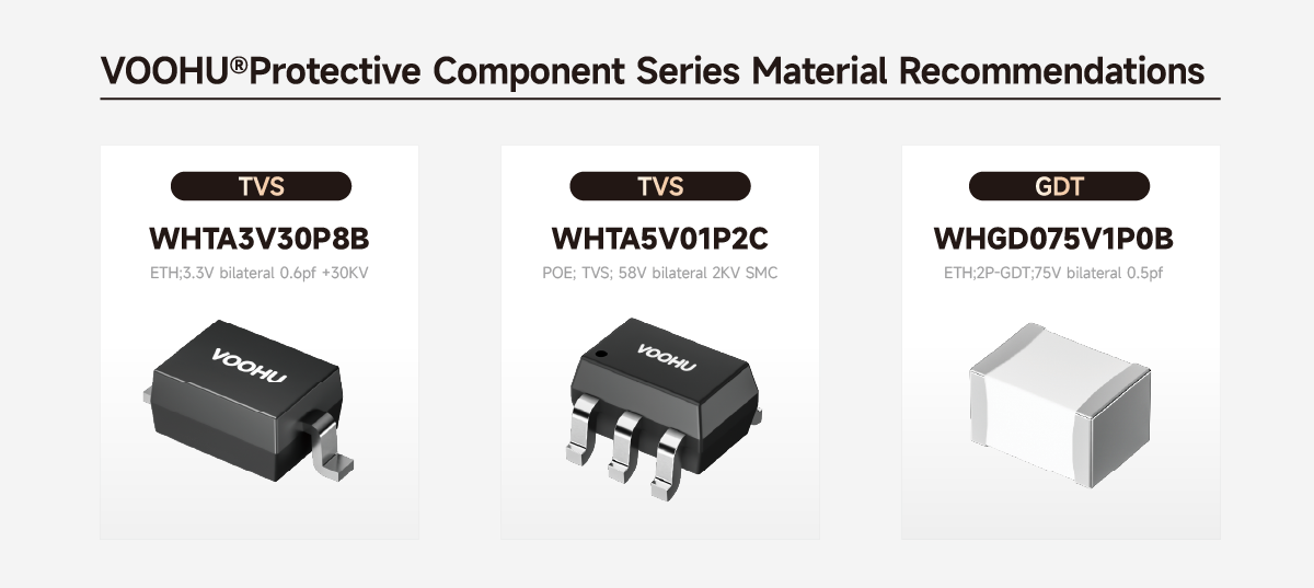
3. TVS
RS-485 通信における TVS の役割: 静電気放電 (ESD) と電気的高速過渡現象 (EFT) を抑制し、雷サージや電源サージによって引き起こされる過渡エネルギーを吸収し、トランシーバー バス ピンを損傷から保護します。
TVS ダイオードは、バス コネクタまたはトランシーバー ピンのできるだけ近くに、短く幅広の配線で配置する必要があります。推奨事項: 差動モード保護のために A ラインと B ラインの間に 1 つの TVS を並列に接続し、さらにコモンモード保護のために各信号ラインから 1 つの TVS をグランドに接続します。
推奨デバイス: RS-485 バスの場合、VOOHU は動作電圧が 6.5 V ~ 24 V の双方向 TVS ダイオードを推奨しています (トランシーバのコモンモード電圧範囲に従って選択)。代表的なモデル:WHTA6V5B、WHTA12V05B、WHTA24V10B。主なパラメータ: 低いクランプ電圧、応答時間 <1ns、ピークパルス電力 400W ~ 1500W。レイアウトでは、TVS は最初に A と B の間 (差動保護)、次に各ラインからグランド (コモンモード保護) まで、バス コネクタのできるだけ近くに配置する必要があります。 VOOHU は、さまざまな電力とスペースの要件を満たすために、SOD123、SOD323、SOT23、およびその他のパッケージを提供しています。
4. コモン-モードチョーク (CMC)
デバイスの原理: コモンモードチョークは、同じコアに同じ巻き数で逆の巻き方向で巻かれた2つのコイルからなる。差動信号に対しては非常に低いインピーダンス (通常 <10Ω)、コモンモード信号に対しては高いインピーダンスを示し、コモンモード電流を効果的に減衰させ、システムの EMC 性能を向上させます。
RS-485 通信における役割:
-
外部環境 (可変周波数ドライブ、スイッチング電源、モーターなど) からのコモンモード放射干渉を抑制し、電磁両立性 (EMC) 性能を向上させます。
-
アンテナとして機能するバス ケーブルから放射されるコモンモード ノイズを低減し、電磁干渉 (EMI) テストに合格するのに役立ちます。
-
TVS および終端抵抗と連携して、完全なイミュニティ保護ネットワークを形成します。
RS-485 通信用の推奨コモン-モード チョーク:
低い DCR、低い差動モード インピーダンス、高いコモンモード除去に重点を置いて、差動信号ライン用に最適化されたコモンモード チョークを選択します。一般的なインピーダンス: 1000Ω @ 100MHz、インダクタンスは約1mH〜10mHで、RS-485通信周波数帯域内で効果的な抑制を保証します。
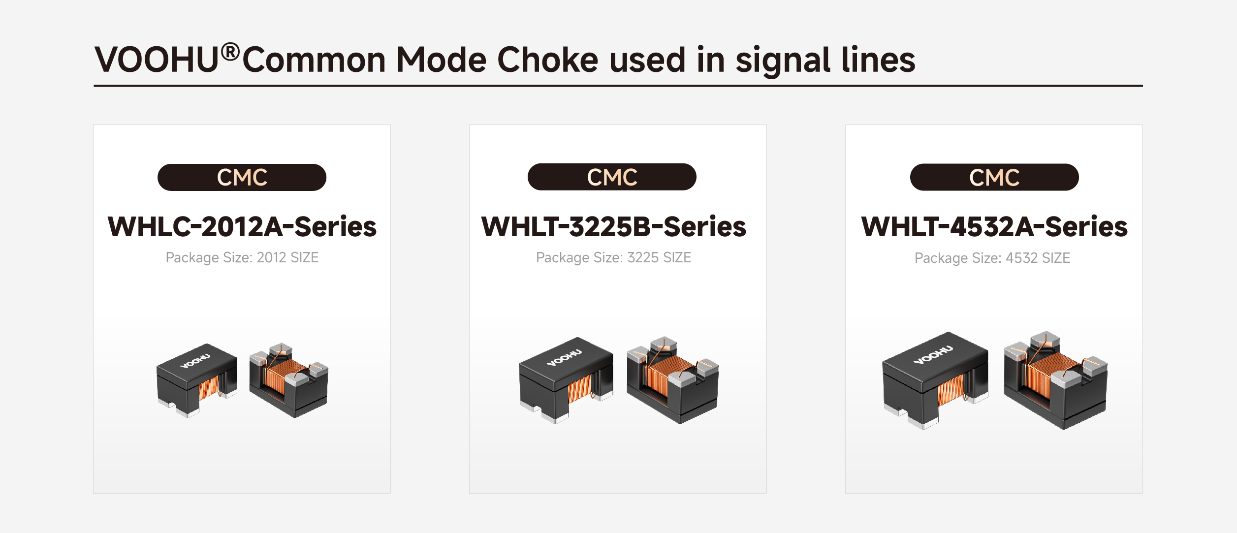
デバイスの選択:
VOOHU 信号コモンモードチョークは、100MHz でのコモンモードインピーダンス、DC 抵抗 (DCR)、およびディファレンシャルモードインピーダンスに重点を置き、RS-485 などの差動バス用に最適化されています。以下のシリーズがおすすめです。
-
2012シリーズ (例: WHLC-2012A-900T0): 90Ω @ 100MHz、0.35Ω、300mA – コンパクトなノードに適しています。
-
3225シリーズ (例: WHAC-3225B-110U0): 550Ω @ 100MHz、0.8Ω、300mA – 一般的な産業用ノード。
-
4532シリーズ (例: WHAC-4532A-220U0): 1200Ω @ 100MHz、1.4Ω、200mA – 高干渉シナリオ用 (例: 可変周波数ドライブの近く)。
5. 終端抵抗とバイアス抵抗
終端抵抗 – 信号反射を排除します。
RS-485 バスは、通常 120Ω の特性インピーダンスを持つツイストペア ケーブルを伝送媒体として使用します。信号がバスの終端に到達すると、インピーダンスの不一致により反射が発生し、信号のリンギングやオーバーシュートが発生し、ビット エラーが発生します。終端抵抗は、ケーブルの特性インピーダンス (通常 120Ω) に等しい値で A ラインと B ラインの間に接続されます。反射エネルギーを吸収し、定在波を抑制し、信号の整合性を確保します。終端抵抗はバスの両端に配置する必要があります。中間ノードには終端抵抗を付けてはなりません。そうしないと、通信エラーが発生する可能性があります。
バイアス抵抗 – バスがアイドル状態のときに定義された状態を維持します。
RS-485 規格では、レシーバ入力しきい値を ±200mV と指定しています。差動電圧が -200mV ~ +200mV の場合、レシーバ出力は不定です。バスがアイドル状態 (すべてのノードが受信モード) の場合、終端抵抗により A-B の差動電圧は 0V になります。特別な対策を講じないと、受信機が不定のレベルを出力し、通信異常を引き起こす可能性があります。この場合、フェールセーフ入力しきい値を内蔵したトランシーバーを選択するか、外部バイアス抵抗を使用してアイドル バスに固定バイアス電圧を生成し (通常、A ラインの電圧を B ラインより 200mV 高くします)、バスのアイドル状態がロジック ハイ レベルとして認識されるようにします。
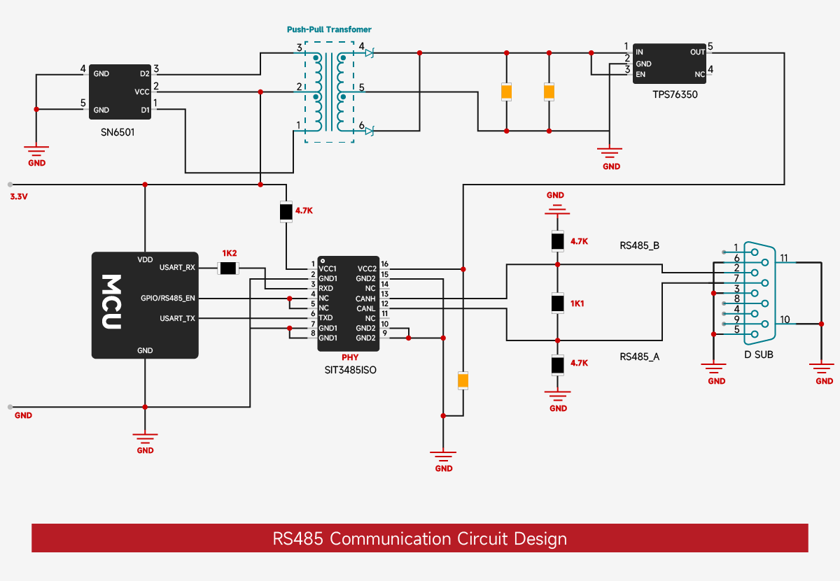
6. 完全な回路設計
上記のモジュールを組み合わせると、一般的な信頼性の高い絶縁型 RS-485 通信回路は次のように設計されます。
レイアウトの原則:
-
絶縁トランシーバを MCU の近くに配置して、一次側のデジタル信号トレースを短くします。
-
バス ピン A および B からコネクタまでの差動、対称、等しい長さの配線を維持し、インピーダンスを約 120Ω に制御します。
-
一次側(コントローラ側):システム 3.3V または 5V が MCU、アイソレータ一次、およびその他の低電圧論理回路に直接供給されます。
-
二次側 (バス側): 絶縁型電源モジュール (DC-DC) を使用して、RS-485 トランシーバー VCC およびアイソレータの二次側専用の 5V_ISO を生成します。
-
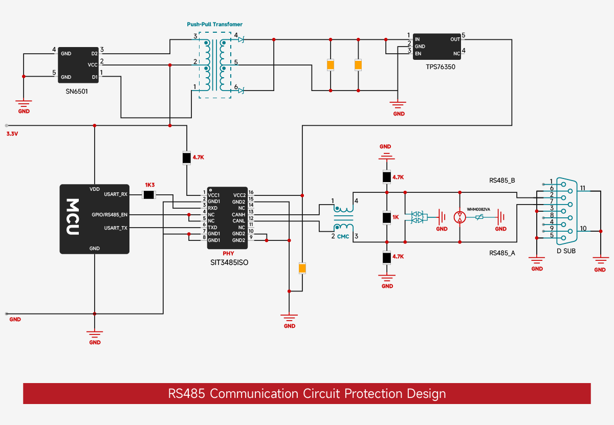
グランドプレーン: プライマリ GND とセカンダリ GND_ISO は完全に分離されています。静電気と高周波ノイズを放電し、浮遊電位の蓄積を防ぐために、10nF の高電圧コンデンサと並列に 1MΩ の抵抗を介してそれらをシャーシ グランド (または保護アース PE) に接続します。
-
保護装置の順序: バスコネクタ → コモンモードチョーク → TVS → トランシーバー A、B ピン。最初に保護し、次にフィルターします。保護デバイスとフィルターは、できるだけインターフェースの近くにしっかりと配置する必要があります。
-
バスの両端に 120Ω の終端抵抗を取り付けます。バスがアイドル状態のときに定義された論理レベルを確保するには、A ラインにプルアップ抵抗を追加し、B ラインにプルダウン抵抗を 1 点 (通常はマスター デバイス側) に追加します。
よくある質問 (FAQ)
Q1: RS-485 バスにはなぜ終端抵抗が必要ですか?値を選択するにはどうすればよいですか?
A1: 終端抵抗はケーブルの特性インピーダンスと一致させ、信号の反射を排除し、リンギングやオーバーシュートを防ぎます。 RS-485 バスは通常、特性インピーダンス 120Ω のツイストペア ケーブルを使用するため、終端抵抗は 120Ω、公差 1% の表面実装抵抗で、バスの最も遠い 2 つの端に配置する必要があります。 VOOHU は 120Ω ±1% の終端抵抗 (0805/1206 パッケージ) を提供しており、BOM を簡素化するためにデュアル抵抗アレイも提供できます。
Q2: RS-485 バスに適切な TVS 保護デバイスを選択するにはどうすればよいですか?
A2: ESD、EFT、雷サージに対して、VOOHU は双方向 TVS ダイオードを推奨しています。トランシーバーのコモンモード電圧範囲 (通常は 6.5V ~ 24V) に基づいて動作電圧を選択します。一般的なモデル:
-
WHTA6V5B (6.5V、3.3V システムに適しています)
-
WHTA12V05B (12V、5V システムに適しています)
-
WHTA24V10B (24V、高サージ保護用)
レイアウトでは、最初に差動モード (A と B の間) 用に TVS を配置し、次にコモン モード (各ラインからグランドへ) 用に、バス コネクタのできるだけ近くに TVS を配置します。 VOOHU TVS ダイオードは、応答時間が 1ns 未満、ピークパルス電力が 400W ~ 1500W で、IEC 61000-4-5 規格を満たしています。
Q3: RS-485 通信においてコモンモードチョークはどのような役割を果たしますか? VOOHUのおすすめは何ですか?
A3: コモンモードチョークは、可変周波数ドライブやスイッチング電源などの外部デバイスからのコモンモード干渉を抑制し、バスからのコモンモード放射を低減し、EMIテストに合格するのに役立ちます。 VOOHU は、3 シリーズの信号-ライン コモン-モード チョークを提供します。
-
2012 シリーズ (例、WHLC-2012A-900T0): 90Ω @ 100MHz、コンパクトなノードに適しています。
-
3225 シリーズ (例、WHAC-3225B-110U0): 550Ω @ 100MHz、一般産業用ノード。
-
4532 シリーズ (例: WHAC-4532A-220U0): 1200Ω @ 100MHz、高干渉シナリオ用。
すべてのモデルは -40 ~ 125°C の幅広い温度をサポートし、AEC-Q200 に準拠しています。
Q4: 絶縁型 RS-485 トランシーバーはどのような場合に必要ですか? VOOHUはどのようなソリューションを提供できるのでしょうか?
A4: コントローラとバスの間に接地電位差がある場合、または安全な絶縁が必要な場合は、絶縁トランシーバを使用する必要があります。 VOOHU は 2 つのソリューションを提供します。
-
ディスクリート: デジタル アイソレータ (例: Si86xx/ISO77xx シリーズ) + 非絶縁トランシーバ (例: MAX485)。
-
統合: シングルチップ絶縁トランシーバー (ISO3082、ADM2483 など)、設計を簡素化します。
さらに、VOOHU は、絶縁電源を生成するプッシュプル絶縁変圧器 (WHST06D02A0 など) を提供し、最大 5000Vrms の絶縁耐圧を備えた完全に絶縁された RS-485 ノードを実現できます。
Q5: RS-485 バスがアイドル状態のときに、未定義のレシーバー出力状態を回避するにはどうすればよいですか?
A5: バスがアイドル状態の場合、終端抵抗により A-B 電圧が 0V に近くなり、受信機は不定のレベルを出力する可能性があります。解決策:
-
フェールセーフ入力しきい値を内蔵したトランシーバー (±200mV しきい値補償を備えたチップなど) を使用してください。
-
外部バイアス抵抗を追加します。A ラインを電源にプルアップし、B ラインをグランドにプルダウンして、アイドル時に A-B 電圧 ≥ +200mV を確保します。
VOOHU はバイアス抵抗の選択計算サービスを提供し、適切な抵抗値を迅速に決定できるように 1kΩ ~ 10kΩ のチップ抵抗器とリファレンス デザインを提供します。