




Pin count
Sets the number of winding taps and the board footprint. Parts with different pin counts are not drop-in replacements for each other.
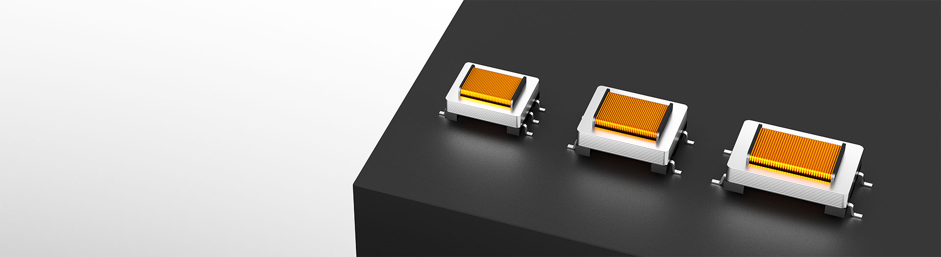
トランス製品
Six pins expose taps on both windings, so a balanced input and a balanced output can share one part. That flexibility costs board area and makes the layout more sensitive, so confirm the pinout and keep the balanced pairs symmetric before you commit.
型番検索・選定
この表では、海外サイトの現行製品データ、公開済みの選定項目、型番別の技術資料リンクを使用しています。
※画像列と型番列は固定されています。横にドラッグしてすべての仕様を確認できます
| 画像 | データシート | 比較 | ダウンロード |
ピン数
|
L/W/H(mm×mm×mm)
|
ACインピーダンス PRI:SEC(Ω)
|
DC抵抗 PRI:SEC(Ω)
|
巻数比(PRI:SEC)
|
実装方式
|
耐電圧(AC)
|
挿入損失(dB)
|
挿入損失(dB)
|
サンプル |
|---|
| 画像 | 型番 | データシート | 比較 | ダウンロード | ピン数 | L/W/H(mm×mm×mm) | ACインピーダンス PRI:SEC(Ω) | DC抵抗 PRI:SEC(Ω) | 巻数比(PRI:SEC) | 実装方式 | 耐電圧(AC) | 挿入損失(dB) | 挿入損失(dB) | サンプル |
|---|---|---|---|---|---|---|---|---|---|---|---|---|---|---|
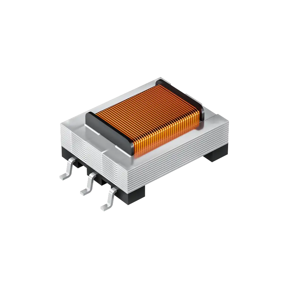 |
WHTT6016 | SPEC | 6ピン | 13.5*10.0*7.50 | 10000:10000 | 1620:1620 | 1±1% | SMD | 3750V | 2 | — |
|
||
|
|
WHTT6010 | SPEC | 6ピン | 14*8*4.4 | 600:412 | 115:115 | - | SMD | 4600V | - | — |
|
||
|
|
WHTT6001 | SPEC | 6ピン | 13.2*8.2*5 | 600:316 | 155:150 | 1±1% | SMD | 1250V | 3.0±0.25 | — |
|
||
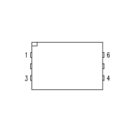 |
WHTT6033 | SPEC | 6ピン | 13.5*9.5*7.5 | 600:430 | 170: 170 | 1±1% | SMD | 3880V | 4.5 | — |
|
||
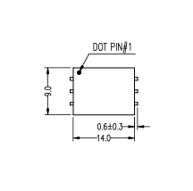 |
WHTT6017 | SPEC | 6ピン | 15.2*9.0*7.5 | なし | 50:50 | 1±2% | SMD | 1500V | - | — |
|
||
 |
WHTT14131 | SPEC | 6ピン | 14*8*4.4 | 600:316 | 30:38 | - | DIP | 1200V | - | — |
|
選択した条件を広げるか、現在の検索条件をクリアしてください。
By pin count
Pin count sets the winding taps and the board footprint, so start from the circuit you have.
選定方法
Work from the source and load impedance outward to the mechanical constraints.
State the source impedance, load impedance, signal level and frequency range, and whether the stage has to convert balanced to unbalanced.
The impedance ratio is the square of the turns ratio. A 600:600 part is 1:1; stepping 600 down to 150 ohm needs a 2:1 turns ratio.
Confirm the maximum signal level the core can carry without saturating, then confirm the dielectric strength the safety case demands.
Match pin count, pin pitch and height against the board, then verify insertion loss and frequency response on your own hardware.
Parameters
Each figure is measured under stated conditions; read the conditions with the number.
Sets the number of winding taps and the board footprint. Parts with different pin counts are not drop-in replacements for each other.
Quoted for a stated frequency, commonly 1 kHz. Read the test frequency with the value; the same part reads differently elsewhere in the band.
Fixes the impedance transformation and the voltage relationship between windings. Impedance ratio equals turns ratio squared.
Winding copper loss. It adds to insertion loss and matters most when the winding also carries a bias current.
The isolation the barrier withstands under the stated test. Choose against the safety requirement, not against the working voltage alone.
Signal lost through the transformer at the stated frequency. Compare candidates at the same frequency or the numbers do not mean the same thing.
比較
Pin count and impedance separate the families more than package size does.
選定表に戻る ↑| ピン数 | 型番数 | L/W/H(mm×mm×mm) | ACインピーダンス PRI:SEC(Ω) | DC抵抗 PRI:SEC(Ω) | 巻数比(PRI:SEC) | 実装方式 | 耐電圧(AC) | 挿入損失(dB) | 挿入損失(dB) | 操作 |
|---|---|---|---|---|---|---|---|---|---|---|
| 4ピン | 17 | 11*8.2*5, 14*8*4.4, 14.5*8.2*5, 14*8.15*5.08, 15.2*8.2*5, 15.2*8*5.08, 15.2*8.2*4.9, 15.6*8.5*5, 18.5*5.08*4.6, 18.2*8.5*4.6, 20.9*8.5*4.5, 20.5*8.5*4.5 | 600:287, 600:290, 600:301, 600:346, 600:400, 600:600, 20000:20000 | 140:170, 105:105, 48:42, 160:135, 157:146, 73:73, 150:150, 160:133, 118:140, 62:3.2, 155:144, 180:160, 141:171, 2370:2820 | 1±1%, 1±2%, 1±3%, 6±1% | SMD | 1000V, 1250V, 1500V, 1650V | 1, 1.3±0.5, 1.5, 2.9±0.1, 3.3±0.2, 3.3±0.25, 3.5, 3.85, -, 2.3 | 未指定 | 絞り込み → |
| 5ピン | 5 | 14.5*8.2*5, 14.5*8.2*4.8, 14.5*8.5*5.08 | 600:600、600:365、600:460、300:600、なし | 120:250, 138:130, 90.5:112:102, 45:55, 65:75 | 1±1%, 1±2%, 2±1% | SMD | 500V, 1000V | 2.8, -, 未指定 | 1.3, 未指定 | 絞り込み → |
| 6ピン | 6 | 13.2*8.2*5, 13.5*9.5*7.5, 13.5*10.0*7.50, 14*8*4.4, 15.2*9.0*7.5 | 600:316、600:412、600:430、10000:10000、なし | 155:150, 115:115, 30:38, 50:50, 170: 170, 1620:1620 | 1±1%, 1±2%, - | SMD、DIP | 1200V, 1250V, 1500V, 3750V, 3880V, 4600V | 2, 3.0±0.25, 4.5, - | 未指定 | 絞り込み → |
用途別確認
Confirm line level, balanced wiring and the impedance ratio the circuit expects.
Documents
Datasheets carry the tested impedance, frequency response and recommended footprint.
代表的な入手可能資料を表示しています。特定のSKUは検索して確認してください。
VOOHUが公開する製品情報は、エンジニアリングチームが確認しています。仕様、ダウンロード資料、技術サポート情報は型番ごとに紐付けられているため、サンプルや見積もりを依頼する前に確認できます。
カテゴリー概要
Two questions come up on almost every audio transformer enquiry: what the part is actually for, and why so many datasheets quote 600 ohm.
型番が決まっている場合は、サンプルまたは見積もりを依頼。
An audio transformer couples a signal magnetically between two windings. Nothing conducts across the barrier, so a ground loop between two pieces of equipment cannot push current through the signal path. That is what removes hum. The second job is impedance matching, so a source drives a load it can actually deliver power into.
600 ohm is a telephone and broadcast line convention rather than a law of physics. It became the reference impedance for balanced audio lines, so parts and equipment were built around it. A 600:600 transformer is a 1:1 isolation part; a 600:150 part steps impedance down by four, which is a 2:1 turns ratio.
Identify the primary, secondary and any centre tap from the datasheet pinout, not from the physical symmetry of the package. Keep the balanced pair symmetric on the board. Then measure insertion loss and frequency response on your own hardware, because the published curve is taken under the datasheet's stated source and load.
よくあるご質問
Answers cover function, the 600 ohm convention, wiring and interchange limits.
Six pins can bring out both ends plus a tap on each winding, so one part serves a balanced stage on the input side and a balanced stage on the output side. It also allows winding halves to be used separately where the datasheet permits it. Read the pinout before assuming any particular arrangement.
No, it is more flexible, which is not the same thing. More pins mean a larger footprint and a layout that is more sensitive to asymmetry between the balanced legs. If the circuit only needs one tap, a five-pin part is easier to lay out and easier to route cleanly.
Keep the two legs of each pair the same length and route them as a pair with a continuous reference plane underneath. Asymmetry between the legs converts common-mode noise into differential noise, which is exactly what the transformer was fitted to avoid. Verify on the board, not on the schematic.
Only if the datasheet says so. Using half a winding changes the effective turns ratio and the level at which the core saturates, and the impedance figure quoted for the full winding no longer applies. Where a part supports it, the datasheet states the ratio for each tap combination.
With a complete part number, send the part number, quantity, delivery region and the date you need it. If you are still selecting, send the source and load impedance, signal level, frequency range and whether both stages must be balanced, and a sales engineer will confirm candidates.
エンジニアサポート
候補型番と、確認が必要な条件をお送りください。候補が明確になった後にサンプル支援を追加でき、商取引に関するご質問も同じ技術相談の中でご相談いただけます。
資料のリビジョンも記載してください
温度、絶縁電圧、PoE電流の条件
ピン数、ピッチ、ピン列間隔
サンプルと評価の優先度確認に使用します
候補と相違点の比較が必要な時期
エンジニア確認により候補型番を選び、相違点をご説明します。
選定表またはエンジニア確認で選んだ型番
試作/パイロット生産/量産
サンプルと量産の時期を分けて記載してください
適合資料、材料宣言、第三者機関レポートなど
サンプル数量、リードタイム、費用は、プロジェクト段階と型番によって異なります。営業担当者より営業日にご回答します。




