




接続方式
中継型、PCB端末型、アダプター型を区別し、背面接続を明確にします。
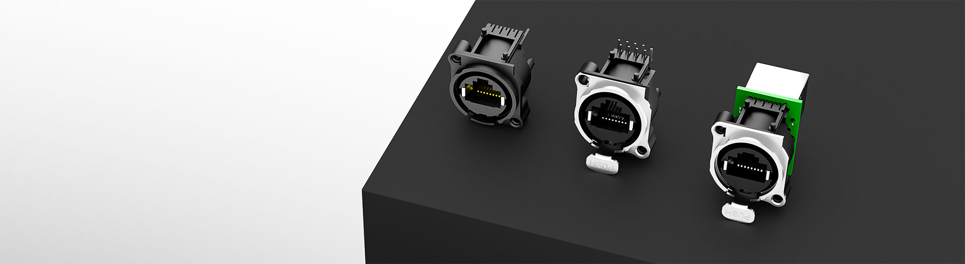
I/Oコネクター製品
This variant mounts directly on the PCB rather than through the panel, with the cable exiting at a right angle. It suits designs where the board sits behind the aperture and the connector carries the mechanical load.
型番検索・選定
この表では、海外サイトの現行製品データ、公開済みの選定項目、型番別の技術資料リンクを使用しています。
※画像列と型番列は固定されています。横にドラッグしてすべての仕様を確認できます
| 画像 | データシート | 比較 | ダウンロード |
配線方式
|
寸法(L×W×H、mm)
|
実装/はんだ付け工程
|
ロック機構
|
挿抜回数(回)
|
接点定格電流(DC)
|
接点定格電圧(AC)
|
動作温度
|
動作湿度
|
サンプル |
|---|
| 画像 | 型番 | データシート | 比較 | ダウンロード | 配線方式 | 寸法(L×W×H、mm) | 実装/はんだ付け工程 | ロック機構 | 挿抜回数(回) | 接点定格電流(DC) | 接点定格電圧(AC) | 動作温度 | 動作湿度 | サンプル |
|---|---|---|---|---|---|---|---|---|---|---|---|---|---|---|
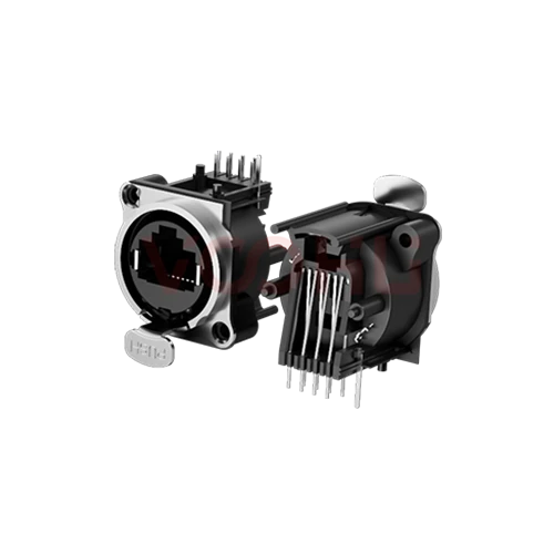 |
WHA9080001051AB35 | SPEC | 90°基板実装 | 25×29.5×25.2 | フローはんだ対応 | ラッチロック | 1000 | 1.5A | 125V | -40 °C~+85 °C | 20~70% |
|
||
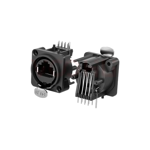 |
WH80000051AB35 | SPEC | 90°基板実装 | 25×29.5×25.2 | フローはんだ対応 | ラッチロック | 1000 | 1.5A | 125V | -40 °C~+85 °C | 20~70% |
|
||
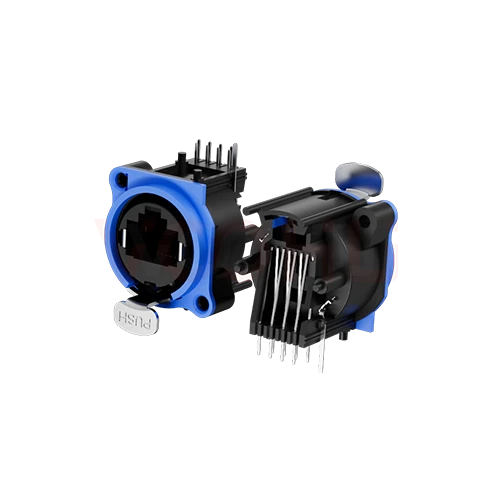 |
WH80000051AB35S | SPEC | 90°基板実装 | 25×29.5×25.2 | フローはんだ対応 | ラッチロック | 1000 | 1.5A | 125V | -40 °C~+85 °C | 20~70% |
|
||
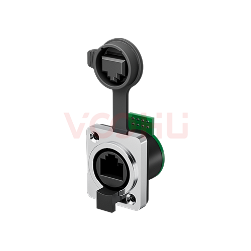 |
WHK6380005V432000 | SPEC | 90°基板実装 | 28×33×34.75 | フローはんだ対応 | ラッチロック | 1000 | 1.5A | 125V | -40 °C~+85 °C | 20~70% |
|
選択した条件を広げるか、現在の検索条件をクリアしてください。
製品ファミリーのクイックリンク
件数は現在公開中の製品データに基づきます。
選定方法
公開項目を順に絞り込み、残った候補を比較して、設計採用前に型番別資料を確認してください。
嵌合部品と、背面インターフェースがケーブル、PCB、アダプターのいずれであるかを特定します。
製品図面でパネル開口、厚さ、取付穴、ケーブルクリアランスを確認します。
ラッチ、内部ロック、ねじ式保持と、型番別の電気、環境、嵌合要件を確認します。
新規設計で組立と嵌合を確認してください。型番が分かっている場合は、数量と時期の要件を直接お知らせください。
主な選定パラメータ
中継型、PCB端末型、アダプター型を区別し、背面接続を明確にします。
図面基準、開口、PCB穴、基板端位置を確認します。外形寸法だけでは取付図の代わりになりません。
ラッチ、内部ロック、ねじ式保持を、嵌合部品と作業性に照らして比較します。
挿抜回数は試験条件と合わせて確認してください。振動定格や防塵・防水等級ではありません。
電流、電圧、温度、湿度を個別に確認してください。コネクター形状だけではシステムの電力能力は決まりません。
| 配線方式 | 型番数 | 寸法(L×W×H、mm) | 実装/はんだ付け工程 | ロック機構 | 挿抜回数(回) | 接点定格電流(DC) | 接点定格電圧(AC) | 動作温度 | 動作湿度 | 操作 |
|---|---|---|---|---|---|---|---|---|---|---|
| 180°ストレートスルー | 3 | 28×33×34.75, 25×30.2×41.5 | 3Mセルフタッピングねじ | ラッチロック | 1000 | 1.5A | 50V, 125V | -30 °C to +80 °C, -40 °C~+85 °C | 20~70%, - | 絞り込み → |
| 180°基板実装 | 4 | 25×29.5×25.2 | フローはんだ対応 | ラッチロック、内部ロック | 1000 | 1.5A | 125V | -40 °C~+85 °C | 20~70% | 絞り込み → |
| 90°アダプター | 1 | 28×33×34.75 | 3Mセルフタッピングねじ | ラッチロック | 1000 | 1.5A | 125V | -40 °C~+85 °C | 20~70% | 絞り込み → |
| 90°基板実装 | 4 | 28×33×34.75, 25×29.5×25.2 | フローはんだ対応 | ラッチロック | 1000 | 1.5A | 125V | -40 °C~+85 °C | 20~70% | 絞り込み → |
| 防水オスコネクター | 1 | 28×33×34.75 | 圧着方式 | スパイラルロック | 1000 | 1.5A | 125V | -40 °C~+85 °C | 20~70% | 絞り込み → |
技術性能・用途適合性
用途への適合性は型番ごとに異なります。カタログ項目で候補を絞り込み、リンク先の技術資料で設計要件への適合を確認してください。
ダウンロード・技術資料
SKUの全部または一部を検索し、製品表に戻らずにデータシート、3Dモデル、PCBフットプリントを開けます。
代表的な入手可能資料を表示しています。特定のSKUは検索して確認してください。
VOOHUが公開する製品情報は、エンジニアリングチームが確認しています。仕様、ダウンロード資料、技術サポート情報は型番ごとに紐付けられているため、サンプルや見積もりを依頼する前に確認できます。
カテゴリー概要
A locking connector solves one specific problem: the standard RJ45 latch is the weakest part of the link.
型番が決まっている場合は、サンプルまたは見積もりを依頼。
The retention on an ordinary RJ45 is a small moulded plastic tab. It breaks, it snags when cables are pulled through, and under vibration it allows enough movement to produce intermittent contact. In an office that is an inconvenience. On a machine, a vehicle or a stage rig it is a fault that is hard to trace.
A locking connector uses a metal shell with a positive mechanical latch, usually a bayonet or threaded arrangement, so the mated pair is held by the housing rather than by a plastic tab. The connection survives vibration and accidental pull on the cable, and it cannot be unplugged without a deliberate action.
The metal housing gives the cable screen somewhere to terminate, which helps emissions and immunity. That only works if the panel mounting provides a defined low impedance path to chassis. A shell left floating, or bonded to signal ground, provides no shielding benefit and can make matters worse.
よくあるご質問・関連ガイド
ここではページの利用手順に沿ってご案内します。型番固有の技術限界は、リンク先の技術資料で確認してください。
A board mount connector solders to the PCB and the board carries the mechanical load from plugging and cable strain. A panel mount version fixes to the enclosure and takes that load into the chassis instead. Choose based on where you want the force to go.
On a connector that locks mechanically and takes cable strain, usually yes. Consider through hole retention posts, a mounting screw or a bracket. A board mounted locking connector transfers significant force to the solder joints if nothing else restrains it.
Work from the drawing. The connector's opening height above the board, the board mounting height and the aperture centre have to line up within tolerance. Check all three before the enclosure is tooled, because adjustment afterwards is expensive.
The self locking mating mechanism works the same way regardless of how the connector is mounted. What changes is where the retaining force is reacted: into the board on this variant, into the chassis on a panel mount version.
With a complete part number, send the part number, quantity, delivery region and the date you need it. If you are still selecting, send the board mounting height, the panel aperture position and the expected mating cycles.
エンジニアサポート
候補型番と、確認が必要な条件をお送りください。候補が明確になった後にサンプル支援を追加でき、商取引に関するご質問も同じ技術相談の中でご相談いただけます。
資料のリビジョンも記載してください
温度、絶縁電圧、PoE電流の条件
ピン数、ピッチ、ピン列間隔
サンプルと評価の優先度確認に使用します
候補と相違点の比較が必要な時期
エンジニア確認により候補型番を選び、相違点をご説明します。
選定表またはエンジニア確認で選んだ型番
試作/パイロット生産/量産
サンプルと量産の時期を分けて記載してください
適合資料、材料宣言、第三者機関レポートなど
サンプル数量、リードタイム、費用は、プロジェクト段階と型番によって異なります。営業担当者より営業日にご回答します。




