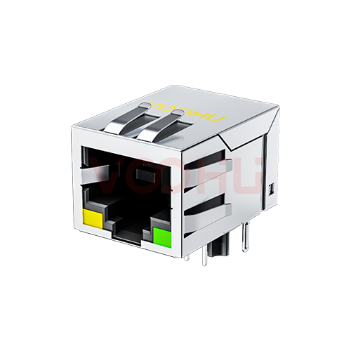
Würth Elektronik 7499211121A Alternative: VOOHU SYT111B127DB1A1DP Comparison
Looking for an alternative to the Würth 7499211121A on a 10/100 PoE port? VOOHU SYT111B127DB1A1DP is a functional alternative — verify with samples in your design. Both are single-port, tab-down MagJacks (RJ45 jacks with integrated magnetics) for 100BASE-TX whose datasheets name IEEE 802.3af, and both schematics put diode bridge rectifiers on the line side with the rectified PoE output on pin 9 (+) and pin 10 (−). The yellow and green LEDs sit on the same pins and the same sides. The layout item to plan for is the shield-pin pair: 15.49 mm apart on the Würth drawing, 15.75 mm apart on the VOOHU drawing.
产品SYT111B127DB1A1DP
7499211121A vs. SYT111B127DB1A1DP: what each datasheet states
The Würth Elektronik column is read from the 7499211121A datasheet, revision 003.000 (2023-07-11). The VOOHU column is read from the SYT111B127DB1A1DP datasheet, revision A0, and from its product page where a cell says so. Page numbers are given in each cell. Dimensions are millimetre values copied from each drawing without rounding; where a row reads "not stated", that document gives nothing for it.
| Item | Würth 7499211121A (source) | VOOHU SYT111B127DB1A1DP (source) |
|---|---|---|
| Speed | 100BASE-TX (DS p3) | 100BASE (DS p1 title); 10/100BASE-TX (product page) |
| Ports / tab | 1 × 1; tab down, read from the front view (DS p1) | 1 × 1; tab down (DS p1 title) |
| Mounting | Through-hole; wave-soldering profile given (DS p1, p4) | Through-hole (DS p1 layout); DIP (product page) |
| Body W × L × H | 16.0 × 21.25 × 13.5 (DS p1) | 16.00 × 21.10 × 13.45 (DS p1) |
| Signal holes | 10 × Ø0.9; 1.27 / 2.54 (DS p1) | 10 × Ø0.89; 1.27 / 2.54 (DS p1) |
| Locating-post holes | 2 × Ø3.25, 11.43 apart (DS p1) | 2 × Ø3.20, 11.43 apart (DS p1) |
| Shield-pin holes | 2 × Ø1.6, 15.49 apart (DS p1) | 2 × Ø1.63, 15.75 apart (DS p1) |
| LED holes | 4 × Ø1.03; 13.25 outer, 8.17 inner (DS p1) | 4 × Ø1.02; 13.26 outer, 8.18 inner (DS p1) |
| PHY-side pins | RD+ 1, RD− 2, CRD 3, CTD 4, TD+ 5, TD− 6 (DS p2) | RD+ 1, RD− 2, CT 3, CT 4, TD+ 5, TD− 6 (DS p2) |
| Cable-side pairs | Data pairs J1/J2 and J3/J6; spare pairs J4/J5 and J7/J8 (DS p2) | J1 TX+, J2 TX−, J3 RX+, J6 RX−; spare pairs J4/J5 and J7/J8 (DS p2) |
| PoE path | Data-pair centre taps and spare pairs into diode bridges; output V+ pin 9, V− pin 10 (DS p2) | Data-pair centre taps and spare pairs into diode bridges; output VC+ pin 9, VC− pin 10 (DS p2) |
| PoE rating as printed | Up to 350 mA per centre tap; compliant with IEEE 802.3af (DS p3) | IEEE 802.3af for PSE or PD applications; line current 350 mA max at 57 V DC continuous (DS p2) |
| LEDs | Yellow left, pins 11 (+) → 12; green right, pins 13 (+) → 14 (DS p2, p3) | Yellow left, pins 11 → 12; green right, pins 13 → 14 (DS p2) |
| LED forward voltage at 20 mA | 1.8–2.4 V (DS p3) | Green 1.85–2.45 V; yellow 1.7–2.2 V (DS p2) |
| OCL | 350 µH min, 100 kHz, 100 mV (DS p3) | 350 µH min, 100 kHz, 100 mV RMS, 8 mA DC bias (DS p2) |
| Turns ratio | 1:1 ± 2% (DS p3) | 1CT:1CT ± 2% (DS p2) |
| Insertion loss, 1–100 MHz | −1 dB max (DS p3) | −1.0 dB max (DS p2) |
| Return loss, min | −18 dB (1–30 MHz), −12 dB (30–60 MHz), −10 dB (60–80 MHz), −10 dB (80–100 MHz) (DS p3) | −20 dB (1–10 MHz), −16 dB (10–30 MHz), −12 dB (30–60 MHz), −10 dB (60–80 MHz) (DS p2) |
| Crosstalk, min | −30 dB (1–100 MHz), −15 dB (100–500 MHz) (DS p3) | −40 dB (1–30 MHz), −35 dB (30–60 MHz), −30 dB (60–100 MHz) (DS p2) |
| Common-mode rejection, min | −30 dB (1–100 MHz), −18 dB (100–250 MHz), −15 dB (250–500 MHz) (DS p3) | −30 dB (1–100 MHz) (DS p2) |
| Isolation test | 1500 V (RMS) min, 1 min (DS p3) | 1500 V AC and 2250 V DC, 6 s, 1 mA, primary to secondary (DS p2) |
| Operating temperature | −40 to +85 °C (DS p3) | −40 to +85 °C (DS p1) |
| Mating cycles | 750 (DS p3) | 750 min (DS p1) |
| Insertion force | not stated | 23 N max (DS p1) |
| Moisture sensitivity level | MSL 1 (DS p3) | not stated |
| EMI gasket | not stated | Yes (product page) |
How does the PoE path of these RJ45 MagJacks compare?
Power is taken from the cable side on both parts. In each schematic, the centre taps of the two data pairs and the spare pairs J4/J5 and J7/J8 run into diode bridges, and the bridge output comes out on pin 9 (positive) and pin 10 (negative). Würth labels these pins V+ and V−; VOOHU labels them VC+ and VC−. A 7499211121A board that feeds its PD controller from pins 9 and 10 therefore keeps the same pins and the same polarity with SYT111B127DB1A1DP. Because the bridges are already inside the jack, read your PD controller's input requirements with that in mind.
The current ratings are worded differently, so they are quoted here as printed rather than merged into one figure. Würth: up to 350 mA per centre tap, compliant with IEEE 802.3af. VOOHU: IEEE 802.3af for PSE or PD applications, with a line current of 350 mA maximum at 57 V DC continuous. Check your PoE budget against each wording under its own condition.
Layout and test items when a 7499211121A footprint takes SYT111B127DB1A1DP
Shield pins, 15.49 mm against 15.75 mm. Würth draws its two shield-pin holes at Ø1.6 mm with 15.49 mm between centres; VOOHU draws them at Ø1.63 mm with 15.75 mm between centres. The other spacings that both drawings print are close: ten signal holes on a 1.27 / 2.54 mm grid, locating posts 11.43 mm apart, and LED-hole spacings within 0.02 mm of each other. Start the overlay of the two drawings at the shield pair, and prove the fit on a sample board.
Hole diameters and the body. The printed diameters differ by a few hundredths of a millimetre — locating posts Ø3.25 / Ø3.20 mm, signal holes Ø0.9 / Ø0.89 mm and LED holes Ø1.03 / Ø1.02 mm (Würth / VOOHU). The body measures 16.0 × 21.25 × 13.5 mm on the Würth drawing and 16.00 × 21.10 × 13.45 mm on the VOOHU drawing. Both parts are through-hole, and Würth also publishes a wave-soldering profile. Try the sample in the enclosure opening as well as on the board.
Hi-pot wording. The two datasheets hold their isolation tests for different lengths of time. Würth gives 1500 V RMS for 1 minute. VOOHU gives two conditions, 1500 V AC and 2250 V DC, each for 6 seconds at 1 mA from primary to secondary. These are separate test conditions and are not converted into one another here; compare each with the method your product standard names. Where a customer drawing quotes the Würth condition, our FAE team can go through the VOOHU condition with you.
LED drive. Yellow on pins 11 (+) and 12 at the left, green on pins 13 (+) and 14 at the right: the LED nets carry over unchanged. Würth gives a single forward-voltage range of 1.8–2.4 V at 20 mA, while VOOHU splits it by colour, green 1.85–2.45 V and yellow 1.7–2.2 V at 20 mA. Recalculate the series resistors from your LED supply with the per-colour VOOHU figures.
Transmission figures. OCL (350 µH minimum at 100 kHz, 100 mV), turns-ratio tolerance (±2%), insertion loss (−1 dB maximum, 1–100 MHz) and common-mode rejection from 1 to 100 MHz (−30 dB) carry the same values on both datasheets; VOOHU adds the 8 mA DC bias used for its OCL measurement. Return loss and crosstalk are specified over different frequency bands, as the table shows, so compare them band by band against the magnetics requirements in your PHY vendor's design guide.
Where a 10/100 RJ45 MagJack with PoE such as SYT111B127DB1A1DP fits
The part suits IEEE 802.3af powered devices with a 100 Mb/s port — IP cameras, door-entry and access-control panels, VoIP phones and small wireless access points — with the jack mounted tab-down in through-hole on boards operating between −40 and +85 °C. For a gigabit PoE port or a PoE+ or PoE++ power level, start from the RJ45 selector or the PoE MagJack selection guide instead.
FAQ
Q1: What is an alternative to the Würth 7499211121A?
VOOHU SYT111B127DB1A1DP is a functional alternative to the Würth Elektronik 7499211121A — verify with samples in your design. The two parts are 1 × 1, tab-down 10/100 RJ45 jacks with integrated magnetics for IEEE 802.3af PoE, with line-side bridge rectifiers, the PoE output on pins 9 (+) and 10 (−), and yellow-left / green-right LEDs. The shield pins are 15.49 mm apart on the Würth drawing and 15.75 mm apart on the VOOHU drawing.
Q2: What is the PoE MagJack pinout of the 7499211121A and SYT111B127DB1A1DP?
The two datasheets use the same pin numbers. Pins 1 and 2 are RD+ and RD−, pins 3 and 4 the PHY-side centre taps (CRD and CTD on the Würth schematic, CT on the VOOHU schematic), pins 5 and 6 TD+ and TD−, pin 9 the positive and pin 10 the negative PoE output, pins 11 (+) and 12 the yellow LED and pins 13 (+) and 14 the green LED. On the cable side, J1/J2 and J3/J6 carry data and J4/J5 and J7/J8 are the spare pairs.
Q3: Does the jack accept PoE on the spare pairs as well as the data pairs?
Both schematics route the data-pair centre taps and the spare pairs J4/J5 and J7/J8 into diode bridges that share one output on pins 9 and 10, so the polarity at pins 9 (+) and 10 (−) does not depend on which pair set carries the power. Both datasheets name IEEE 802.3af. For a supply outside that standard, such as a passive 24 V scheme, discuss it with our FAE team against the VOOHU rating of 350 mA maximum at 57 V DC.
Q4: Are all RJ45 connectors the same?
No, and two jacks built for the same job show why. The 7499211121A and SYT111B127DB1A1DP share pin numbers, LED positions and PoE output pins, yet their drawings put the shield pins 15.49 mm and 15.75 mm apart and print slightly different hole diameters, and their return-loss and crosstalk limits are written over different frequency bands. Compare the drawings and datasheets line by line and confirm with a sample before one jack goes into another's footprint.
Send your 7499211121A layout with a sample request
Attach the 7499211121A footprint from your board and the PD section of your schematic to the sample request form. Samples are available for evaluation, and selected parts are free of charge. Our FAE team will be glad to confirm the options for your project. Our FAE team can suggest suitable parts and help check the design — for SYT111B127DB1A1DP, the shield-pin spacing against your pads, the pin 9 and pin 10 connection to your PD controller, and the hi-pot condition your product standard calls for.
VOOHU supplies RJ45 and SFP connectors, LAN and PoE transformers and common mode chokes from Suzhou, China, to more than 1,500 customers.
Other tab-down jacks with integrated magnetics and a 350 mA PoE rating are in the RJ45 connector selector, which opens with those three filters set.
Related product: SYT111B127DB1A1DP — 1 × 1 tab-down 10/100BASE-TX RJ45 jack with integrated magnetics, IEEE 802.3af PoE through line-side bridge rectifiers, yellow / green LEDs, −40 to +85 °C, through-hole. For the gigabit Würth part in the same family, see the 7499111121A comparison.
方案/solution-poe/