




Common mode impedance
What the choke presents to common mode noise, quoted at a stated frequency. Compare candidates at the same frequency or the numbers do not correspond.
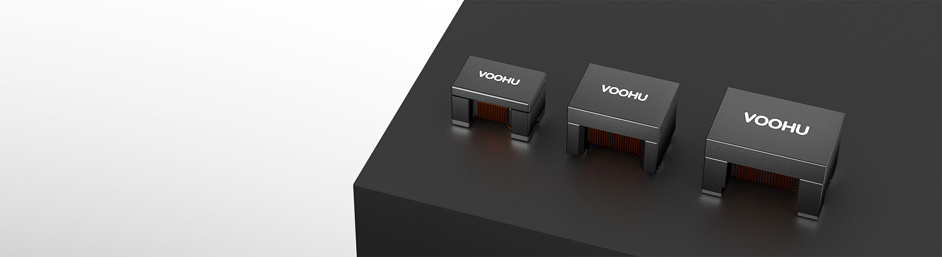
Produits d’inductance
WHLC2012A is another option in the 2012 size band, for differential interfaces where board area is the binding constraint. Compare the impedance curve against your failing band, then confirm the link still meets its eye and return loss targets.
Recherche et sélection de références
Le tableau utilise les fiches produits actuelles du site anglophone, les critères de sélection publiés et les liens vers les fichiers techniques propres à chaque référence.
* Colonnes Image et Référence figées · faites glisser horizontalement pour consulter toutes les caractéristiques
| Image | Fiche technique | Comparer | Téléchargements |
Taille
|
Impédance de mode commun à 10 MHz, min. (Ω)
|
Impédance de mode commun typ. (Ω)
|
Inductance (μH), +50/−30 %
|
RDC (Ω), max.
|
Inductance de fuite (nH), typ.
|
Résistance d’isolement (MΩ), min.
|
Courant nominal, max.
|
Tension nominale (V), max.
|
Échantillon |
|---|
| Image | Référence | Fiche technique | Comparer | Téléchargements | Taille | Impédance de mode commun à 10 MHz, min. (Ω) | Impédance de mode commun typ. (Ω) | Inductance (μH), +50/−30 % | RDC (Ω), max. | Inductance de fuite (nH), typ. | Résistance d’isolement (MΩ), min. | Courant nominal, max. | Tension nominale (V), max. | Échantillon |
|---|---|---|---|---|---|---|---|---|---|---|---|---|---|---|
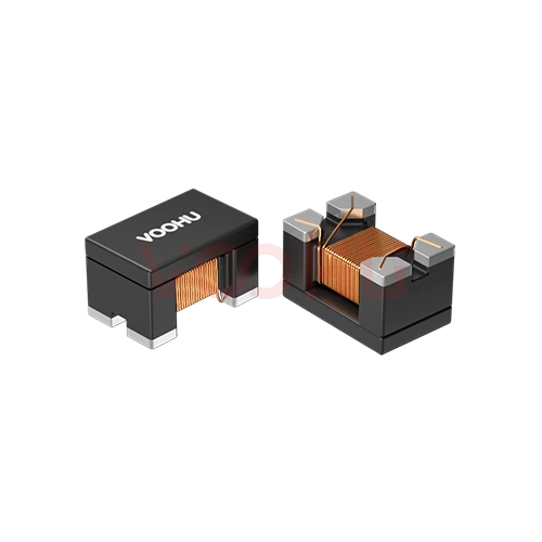 |
WHLC-2012A-121T1 | SPEC | 2012 | - | 120 | - | 0.3 | - | 10 | 400mA | 125 |
|
||
|
|
WHLC-2012A-381T0 | SPEC | 2012 | - | 380 | - | 0.45 | - | 10 | 300mA | 50 |
|
||
|
|
WHLC-2012A-900T0 | SPEC | 2012 | - | 90 | - | 0.35 | - | 10 | 300mA | 50 |
|
||
|
|
WHLC-2012A-181T0 | SPEC | 2012 | - | 180 | - | 0.35 | - | 10 | 300mA | 50 |
|
||
|
|
WHLC-2012A-261T0 | SPEC | 2012 | - | 260 | - | 0.4 | - | 10 | 300mA | 50 |
|
||
|
|
WHLC-2012A-361T1 | SPEC | 2012 | - | 360 | - | 0.45 | - | 10 | 300mA | 50 |
|
||
|
|
WHLC-2012A-801T0 | SPEC | 2012 | - | 800 | - | 0.88 | - | 10 | 300mA | 50 |
|
||
|
|
WHLC-2012A-102T0 | SPEC | 2012 | - | 1000 | - | 1.3 | - | 10 | 300mA | 50 |
|
||
|
|
WHLC-2012A-122T0 | SPEC | 2012 | - | 1200 | - | 1.5 | - | 10 | 300mA | 50 |
|
||
|
|
WHLC-2012A-750C | SPEC | 2012 | - | 75 | - | 0.55 | - | 10 | 280mA | 50 |
|
||
|
|
WHAC-2012A-801T0 | SPEC | 2012 | - | 800 | - | 0.88 | - | 10 | 300mA | 50 |
|
||
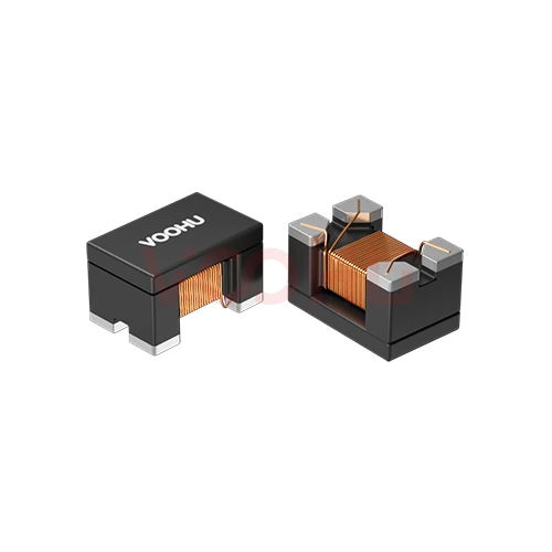 |
WHAC-2012A-900T0 | SPEC | 2012 | - | 90 | - | 0.35 | - | 10 | 300mA | 50 |
|
||
|
|
WHLC-2012A-121T0 | SPEC | 2012 | - | 120 | - | 0.3 | - | 10 | 400mA | 50 |
|
Élargissez les filtres sélectionnés ou effacez la recherche en cours.
By interface
The interface sets the data rate and therefore what the choke is allowed to do to the signal.
Comment sélectionner
Interface first, then the failing band, then signal integrity, then the footprint.
USB, CAN bus, Ethernet and HDMI each set a data rate and a signalling scheme. That determines how much the choke is allowed to affect the signal.
Read the frequency range where the radiated or conducted scan exceeds the limit, then look for a part whose impedance is high across that range.
Check the impedance peak does not sit near your signal's fundamental, and that DC resistance does not add unacceptable loss on the pair.
Measure the eye diagram and return loss on your own board. Datasheet curves are taken in a reference fixture, not in your layout.
Parameters
Impedance is quoted at a frequency; so is everything else that matters here.
What the choke presents to common mode noise, quoted at a stated frequency. Compare candidates at the same frequency or the numbers do not correspond.
Matters when the pair also carries bias or power, as on some bus and PoE-adjacent designs. On a pure signal pair it is rarely the binding constraint.
Adds loss in the signal path and causes a voltage drop where the pair carries current. Read the maximum figure rather than a typical value.
How much of the wanted signal the part removes. Low values matter more as the data rate rises; verify by measurement rather than by datasheet alone.
Sets the board area and the spacing available between the differential traces. Smaller packages ease layout but usually offer lower impedance.
Asymmetry between the two windings turns common mode into differential noise. It is the reason a choke can make an eye diagram worse rather than better.
Comparer
Package size and impedance level separate the families; the interface decides which fits.
Revenir au sélecteur ↑| Taille | Références | Impédance de mode commun à 10 MHz, min. (Ω) | Impédance de mode commun typ. (Ω) | Inductance (μH), +50/−30 % | RDC (Ω), max. | Inductance de fuite (nH), typ. | Résistance d’isolement (MΩ), min. | Courant nominal, max. | Tension nominale (V), max. | Action |
|---|---|---|---|---|---|---|---|---|---|---|
| 2012 | 13 | - | 120, 1200, 1000, 800, 380, 360, 260, 180, 90, 75 | - | 0.3, 0.35, 0.4, 0.45, 0.55, 0.88, 1.3, 1.5 | - | 10 | 280mA, 300mA, 400mA | 50, 125 | Filtrer → |
| 3225 | 6 | 300, 500, 1000, 2200, - | 550, 1100, 2600, 5100, - | 11, 22, 51, 80, 100, 200 | 0.8, 1, 1.6, 2.5, 4, 4.9 | 50, 70, 130, 180, - | 10 | 70mA, 150mA, 200mA, 250mA, 300mA | 80 | Filtrer → |
| 4532 | 21 | 300, 500, 1000, 2000, - | 600, 1200, 2800, 5800, 90±25%, 420±25%, 600±25%, 800±25%, 1000±25%, 1400±25%, 1400 | 11, 22, 51, 100, - | 0.25, 1.2, 1.4, 1.8, 2.5, 39, 60, 82, 89, 113, 148 | 50, 80, 150, 200, - | 10 | 150mA, 200mA, 250mA, 700mA, 1.0A, 1.5A, 1.8A, 2.0A, 2.2A, 3.0A | 50 | Filtrer → |
Analyse de l’application
Confirm the interface, the data rate and whether the pair also carries bias current.
Documents
Datasheets carry the impedance curve, DC resistance and recommended land pattern.
Affichage de jeux de fichiers disponibles représentatifs. Recherchez un SKU précis.
Le contenu produit publié par VOOHU est vérifié par son équipe technique. Les caractéristiques, les téléchargements et les informations d’assistance technique sont associés à des références précises afin que vous puissiez les vérifier avant de demander des échantillons ou un devis.
Présentation de la catégorie
On a power line the choke only has to pass current. On a signal pair it has to pass a waveform intact, which makes the selection harder.
Discuter d’une nouvelle conception
Contacter l’équipe FAE pour une évaluation de remplacement.
Vous avez déjà une référence ? Demander des échantillons ou un devis.
A choke that works on a CAN bus can wreck a USB link, because the data rates differ by orders of magnitude. The interface sets how much insertion loss and how much impedance in the signal path the link can tolerate. Decide the interface and its rate before you start comparing impedance figures.
You want high common mode impedance across the band that fails your scan, and low impact at your signal's own frequencies. If the peak sits near the fundamental, the choke will attenuate the wanted signal as well as the noise. Read the curve, locate your two frequencies on it, and check they are far apart.
Real parts are never perfectly symmetric. Any imbalance between the two windings converts common mode noise into differential noise, which lands directly on the signal. This is why a choke sometimes makes an eye diagram worse. It cannot be predicted from the datasheet, so measure the eye and return loss on your own board.
FAQ
Answers cover interface fit, eye diagram impact and how to compare candidates.
Read each part's common mode impedance at the frequency your scan fails, compare maximum DC resistance, then check the recommended land pattern and the symmetry of the differential routing through the part. Finally verify on the target board, because layout changes the measured outcome.
Compact parts suit differential interfaces where trace spacing is constrained. Whether a given part fits a specific interface depends on its impedance curve and insertion loss, so send the interface and data rate and our engineers will confirm which candidates are appropriate.
No. Prefixes identify naming families, not performance tiers. Reading a ranking into the letters is a common mistake. Compare the actual impedance at the frequency you care about, along with DC resistance and the datasheet's stated test conditions.
Re-run the emission scan to confirm the failing band is now within limit, and measure the eye diagram and return loss to confirm the signal has not degraded. Both checks matter, because a choke that fixes emissions while breaking the link has not solved the problem.
With a complete part number, send the part number, quantity, delivery region and the date you need it. If you are still selecting, send the interface, the data rate and the frequency band where your scan fails, and a sales engineer will confirm candidates first.
Assistance technique
Envoyez la référence candidate et la condition à examiner. Vous pourrez demander des échantillons une fois la sélection précisée ; les questions commerciales peuvent être abordées au cours du même échange technique.
Indiquez la révision du document
Température, tension d’isolement et conditions de courant PoE prises comme référence
Nombre de broches, pas et espacement entre les rangées de broches
Pour faciliter la priorisation des échantillons et de l’évaluation
Date à laquelle vous avez besoin de références candidates et d’un comparatif des différences
L’analyse technique identifie les références candidates et explique les différences.
Issues du sélecteur ou de l’analyse technique
Prototypage / présérie / production
Précisez séparément les délais des échantillons et de la production
Documents de conformité, déclarations de matières ou rapports de tiers
La quantité d’échantillons, le délai et le coût dépendent de la phase du projet et de la référence. L’équipe commerciale répond les jours ouvrés.




