




Port notation
A figure such as 5+1 means five external ports plus one host uplink. A single figure such as 5 or 8 means external ports only, with no separate uplink.
Gamme de circuits d’interface Ethernet
The range covers 100M and gigabit switching from three to ten ports, with or without a host uplink. Start from the port topology your design needs, because whether the host takes part in forwarding decides the series long before speed or package does.
Recherche et sélection de références
Le tableau utilise les fiches produits actuelles du site anglophone, les critères de sélection publiés et les liens vers les fichiers techniques propres à chaque référence.
* Colonnes Image et Référence figées · faites glisser horizontalement pour consulter toutes les caractéristiques
| Image | Fiche technique | Comparer | Téléchargements |
Série
|
Débit de données
|
Ports
|
Mode d’interface
|
Tension de l’interface MAC
|
Tension d’alimentation externe
|
Port cuivre
|
Port optique
|
Température
|
Boîtier
|
Taille
|
Échantillon |
|---|
| Image | Référence | Fiche technique | Comparer | Téléchargements | Série | Débit de données | Ports | Mode d’interface | Tension de l’interface MAC | Tension d’alimentation externe | Port cuivre | Port optique | Température | Boîtier | Taille | Échantillon |
|---|---|---|---|---|---|---|---|---|---|---|---|---|---|---|---|---|
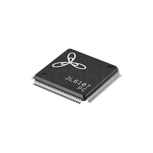 |
JL6107-PC | SPEC | Série JL6107 | 1G | 5+2 | MII | 1.8V | 1.1V | 10 Base-T | NA | 0~70℃ | LQFP128 | 14*14 mm |
|
||
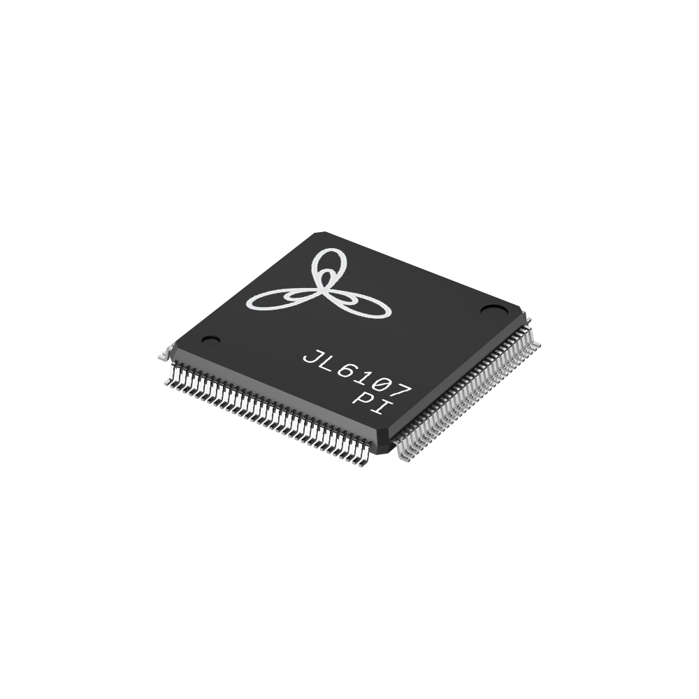 |
JL6107-PI | SPEC | Série JL6107 | 1G | 5+2 | MII | 1.8V | 1.1V | 10 Base-T | NA | -40~85℃ | LQFP128 | 14*14 mm |
|
||
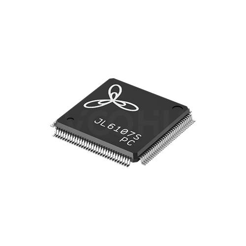 |
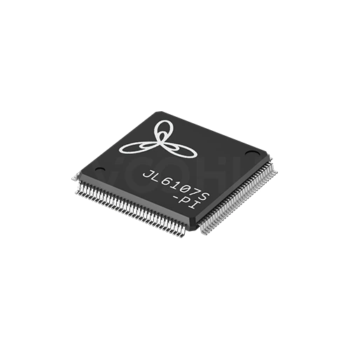
JL6107S-PC | SPEC | Série JL6107 | 1G | 5+2 | MII | 1.8V | 3.3V(1.1V)¹ | 10 Base-T | 1000 Base-X | 0~70℃ | LQFP128 | 14*14 mm |
|
||
 |
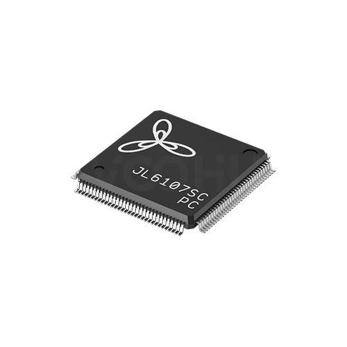
JL6107S-PI | SPEC | Série JL6107 | 1G | 5+2 | MII | 1.8V | 3.3V(1.1V)¹ | 10 Base-T | 1000 Base-X | -40~85℃ | LQFP128 | 14*14 mm |
|
||
 |
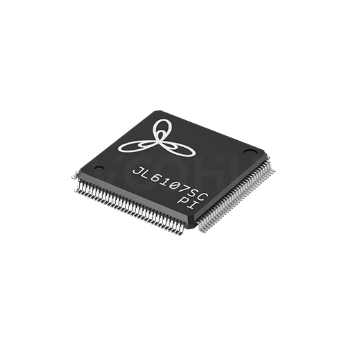
JL6107SC-PC | SPEC | Série JL6107 | 1G | 5+2 | MII | 1.8V | 3.3V(1.1V)¹ | 10 Base-T | 1000 Base-X | 0~70℃ | LQFP128 | 14*14 mm |
|
||
 |
JL6107SC-PI | SPEC | Série JL6107 | 1G | 5+2 | MII | 1.8V | 3.3V(1.1V)¹ | 10 Base-T | 1000 Base-X | -40~85℃ | LQFP128 | 14*14 mm |
|
Élargissez les filtres sélectionnés ou effacez la recherche en cours.
By port topology
Port notation such as 5+1 means five external ports plus one host uplink.
Comment sélectionner
Topology first, then speed, then the supply rails, then package and thermals.
Count the external ports you need, then decide whether the host has to send and receive traffic. If it does, you need a device with an uplink port.
The range covers 100M and gigabit. There are no 2.5G or faster devices here, so if the design needs those speeds, say so at enquiry.
Most devices need a low voltage core rail alongside the main supply. Confirm the rails and their sequencing before the power tree is fixed.
Packages run from QFN48 at 6 by 6 up to TQFP176 at 20 by 20 millimetres. Higher port counts concentrate more heat in one device.
Parameters
Port notation and the supply requirement are the two figures most often misread.
A figure such as 5+1 means five external ports plus one host uplink. A single figure such as 5 or 8 means external ports only, with no separate uplink.
100M on the JL51xx series, gigabit on the JL61xx series. Every device also supports 10Base-T on copper for legacy links.
MII on most devices with an uplink, RMII on the JL5104. Devices listed as NA have no dedicated host interface at all.
Typically a 3.3 volt main supply with a 1.1 volt core rail, or 1.1 volt alone on some gigabit parts. Missing a rail prevents the device starting.
1000Base-X appears on the JL6110 and on the S variants of the JL6107. Other devices in the range are copper only.
NC and PC suffixes cover 0 to 70 degrees; NI and PI cover minus 40 to 85. Not every series offers both grades.
Comparer
Port count and uplink presence separate the series more than speed does.
Revenir au sélecteur ↑| Série | Références | Débit de données | Ports | Mode d’interface | Tension de l’interface MAC | Tension d’alimentation externe | Port cuivre | Port optique | Température | Boîtier | Taille | Action |
|---|---|---|---|---|---|---|---|---|---|---|---|---|
| Série JL5104 | 2 | 100M | 3+1 | RMII | 3.3V | 3.3V(1.1V)¹ | 10 Base-T | NA | 0~70℃, -40~85℃ | QFN48 | 6*6 mm | Filtrer → |
| Série JL5105 | 2 | 100M | 5 | NA | NA | 3.3V(1.1V)¹ | 10 Base-T | NA | 0~70℃, -40~85℃ | QFN48 | 6*6 mm | Filtrer → |
| Série JL5106 | 2 | 100M | 5+1 | MII | 3.3V | 3.3V(1.1V)¹ | 10 Base-T | NA | 0~70℃, -40~85℃ | QFN64 | 9*9 mm | Filtrer → |
| Série JL5108 | 2 | 100M | 8 | NA | NA | 3.3V(1.1V)¹ | 10 Base-T | NA | 0~70℃, -40~85℃ | QFN64 | 9*9 mm | Filtrer → |
| Série JL5109 | 1 | 100M | 8+1 | MII | 3.3V | 3.3V(1.1V)¹ | 10 Base-T | NA | 0~70℃ | QFN88 | 10*10 mm | Filtrer → |
| Série JL5110 | 1 | 100M | 8+2 | MII | 3.3V | 3.3V(1.1V)¹ | 10 Base-T | NA | 0~70℃ | QFN88 | 10*10 mm | Filtrer → |
| Série JL6105 | 1 | 1G | 5 | NA | NA | 1.1V | 10 Base-T | NA | 0~70℃ | QFN88 | 10*10 mm | Filtrer → |
| Série JL6107 | 6 | 1G | 5+2 | MII | 1.8V | 1.1V, 3.3V(1.1V)¹ | 10 Base-T | NA, 1000 Base-X | 0~70℃, -40~85℃ | LQFP128 | 14*14 mm | Filtrer → |
| Série JL6108 | 1 | 1G | 8 | NA | NA | 1.1V | 10 Base-T | NA | 0~70℃ | LQFP128 | 20*14 mm | Filtrer → |
| Série JL6110 | 2 | 1G | 8+2 | MII | 3.3V | 1.1V | 10 Base-T | 1000 Base-X | 0~70℃, -40~85℃ | TQFP176 | 20*20 mm | Filtrer → |
Analyse de l’application
Confirm the port topology, whether the host must manage traffic, and the environment.
Documents
Datasheets carry the supply sequencing, pinout and reference schematic per device.
Affichage de jeux de fichiers disponibles représentatifs. Recherchez un SKU précis.
Le contenu produit publié par VOOHU est vérifié par son équipe technique. Les caractéristiques, les téléchargements et les informations d’assistance technique sont associés à des références précises afin que vous puissiez les vérifier avant de demander des échantillons ou un devis.
Présentation de la catégorie
Almost every selection question on switch ICs comes down to the port notation and whether the host controller needs to be on the network.
Discuter d’une nouvelle conception
Contacter l’équipe FAE pour une évaluation de remplacement.
Vous avez déjà une référence ? Demander des échantillons ou un devis.
The first figure is external ports facing the outside world. The figure after the plus is a host uplink, a dedicated interface for the controller on the same board. A device listed as 5 has five external ports and no uplink, so the host cannot send or receive traffic through it. That distinction eliminates half the range.
If the product only has to move traffic between its own front panel ports, a device with external ports only is simpler and cheaper to lay out. If the host has to participate, for management, for remote access or because it originates data, you need an uplink and the host must provide the matching MII or RMII interface.
Most devices here need more than one rail: commonly 3.3 volts for the main supply and around 1.1 volts for the core, and some gigabit parts run the core alone. Missing a rail, or sequencing them wrongly, prevents the device starting. Confirm the rails and sequence before the power tree is committed.
FAQ
Answers cover port notation, uplinks, supply rails and fibre support.
Five external ports facing the network, plus one dedicated host uplink for the controller on the same board. A device listed with a single figure, such as 5 or 8, has that many external ports and no uplink, which means the host cannot send or receive traffic through the switch at all.
Only if the host controller has to be on the network, whether to manage the switch, to be reachable remotely, or because it originates traffic. If the product only forwards between its own front panel ports, a device without an uplink is simpler to design and lay out.
100M on the JL51xx series and gigabit on the JL61xx series, with 10Base-T supported on copper throughout. There are no 2.5G, 5G or 10G devices in this range. If your design needs multi-gigabit switching, tell us at enquiry and we will confirm what is available.
1000Base-X is supported on the JL6110 and on the S variants of the JL6107 series. The remaining devices are copper only. Because fibre support varies between variants within a series, check the complete part number rather than relying on the series name.
Most need a 3.3 volt main supply together with a core rail around 1.1 volts, while some gigabit parts run from the core rail alone. The datasheet states both the rails and the sequence they must come up in. A missing or mis-sequenced rail usually prevents the device starting.
Devices with two uplinks allow one link to the host and one to a second switch. Before doing so, estimate how much traffic crosses between the two devices, because everything that crosses has to pass through the cascade link, which can become the bottleneck for the whole design.
It rises with port count and speed. The largest devices here are TQFP176 at 20 by 20 millimetres with ten gigabit ports, which concentrates significant power in one package. Follow the datasheet thermal pad guidance and measure the case temperature at full load in the real enclosure.
With a complete part number, send the part number, quantity, delivery region and the date you need it. If you are still selecting, send the external port count, whether the host needs an uplink, the required speed, any fibre requirement and the temperature range.
Assistance technique
Envoyez la référence candidate et la condition à examiner. Vous pourrez demander des échantillons une fois la sélection précisée ; les questions commerciales peuvent être abordées au cours du même échange technique.
Indiquez la révision du document
Température, tension d’isolement et conditions de courant PoE prises comme référence
Nombre de broches, pas et espacement entre les rangées de broches
Pour faciliter la priorisation des échantillons et de l’évaluation
Date à laquelle vous avez besoin de références candidates et d’un comparatif des différences
L’analyse technique identifie les références candidates et explique les différences.
Issues du sélecteur ou de l’analyse technique
Prototypage / présérie / production
Précisez séparément les délais des échantillons et de la production
Documents de conformité, déclarations de matières ou rapports de tiers
La quantité d’échantillons, le délai et le coût dépendent de la phase du projet et de la référence. L’équipe commerciale répond les jours ouvrés.




