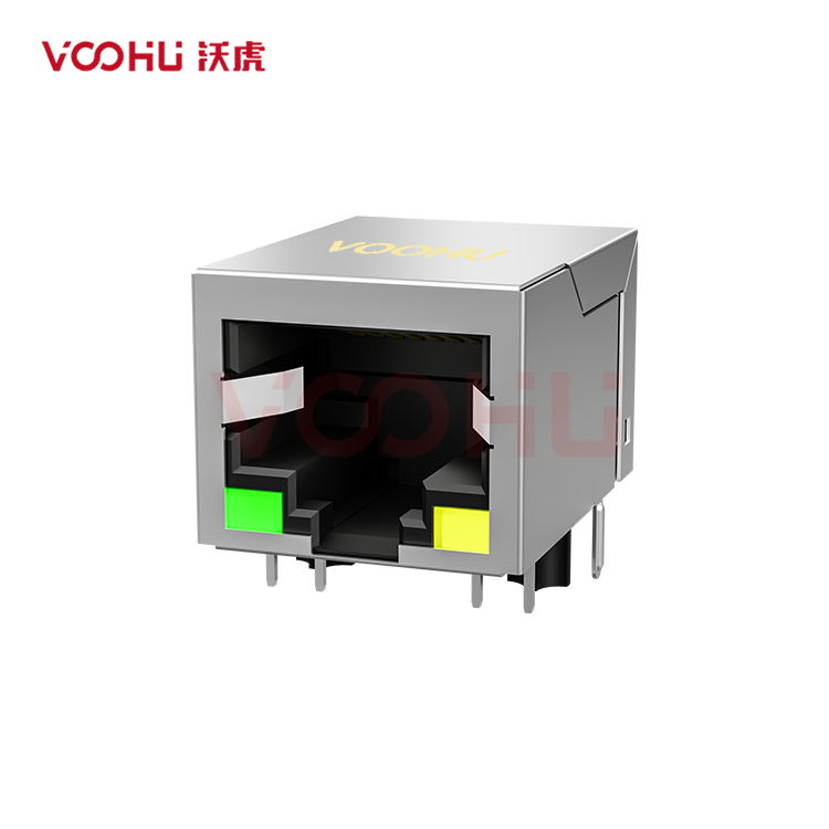
HanRun HY911105AE Alternative: VOOHU SYT111B002BA2A1D Comparison
For a board laid out around the HanRun HY911105AE, the VOOHU SYT111B002BA2A1D is a functional alternative — verify with samples in your design. Each is a 1×1 RJ45 jack with integrated magnetics (a MagJack), tab down, for 10/100BASE-TX and rated −40 to +85 °C. On the two published schematics, pins 1–8 carry the same functions, the green LED (pin 9 to 10) sits on the left and the yellow LED (pin 12 to 11) on the right. OCL, return loss and crosstalk are printed with the same values. Once the two drawings face the same way, the signal holes, the LED holes and the 11.43 mm post spacing fall in the same places. Two hole callouts differ: the shield-pin holes are 15.49 mm apart on the HanRun drawing and 15.75 mm apart on the VOOHU drawing, and the locating-post holes are Ø3.25 mm against Ø3.20 mm.
[Product] SYT111B002BA2A1D
HY911105AE vs. SYT111B002BA2A1D: specifications and hole patterns side by side
The HanRun column comes from the HY911105AE datasheet, Rev A, as hosted by LCSC. It is two pages long: the electrical table and schematic on page 1, the outline, recommended PCB layout and LED table on page 2. The VOOHU column comes from the SYT111B002BA2A1D datasheet, revision A0, which runs to four pages; this comparison uses page 1 (outline, hole pattern, materials), page 3 (schematic, electrical table, LEDs) and page 4 (wave-solder profile). Dimensions are in millimetres. A cell marked "not stated" is one the datasheet leaves empty. Where the text below derives a number by arithmetic from two printed dimensions, it says so at that point.
| Parameter | HanRun HY911105AE (datasheet Rev A) | VOOHU SYT111B002BA2A1D (DS rev A0) |
|---|---|---|
| Type | Single port, integrated magnetics and LEDs, 10/100Base-TX (p1 title); tab down (p2 front view) | Tab-down 1×1, 10/100BASE (p1 title block); 10/100BASE-TX (product page) |
| Chip-side pins | TD+ 1, TD− 2, RD+ 3, RD− 6; 4 and 5 drawn as the TD and RD centre taps (not labelled); 7 NC; 8 chassis ground (p1) | TD+ 1, TD− 2, RD+ 3, RD− 6; CT 4 and CT 5; 7 not connected; 8 GND (p3) |
| Cable-side termination | 4 × 75 Ω and 1000 pF / 2 kV to chassis ground (p1) | 4 × 75 Ω and 1000 pF / 2 kV to GND (p3) |
| OCL | 350 µH min at 100 kHz, 100 mV, 8 mA DC (p1) | 350 µH min at 100 kHz, 100 mV, 8 mA DC (p3) |
| Insertion loss | −1.0 dB max, 300 kHz–100 MHz (p1) | −1.0 dB max, 1–100 MHz (p3) |
| Return loss | −20 / −16 / −12 / −10 dB min at 1–10 / 10–30 / 30–60 / 60–80 MHz (p1) | −20 / −16 / −12 / −10 dB min at 1–10 / 10–30 / 30–60 / 60–80 MHz (p3) |
| Crosstalk | −40 / −35 / −30 dB min at 1–30 / 30–60 / 60–100 MHz (p1) | −40 / −35 / −30 dB min at 1–30 / 30–60 / 60–100 MHz (p3) |
| Common-mode rejection | −30 dB min at 1–50 MHz; −20 dB min at 50–150 MHz (p1) | −30 dB min at 1–100 MHz (p3) |
| Isolation | 1500 Vrms, UTP side to chip side; duration and current not stated (p1) | 1500 V AC and 2250 V DC, 6 s, 1 mA, primary to secondary (p3) |
| Operating / storage temperature | −40 to +85 °C / not stated (p1) | −40 to +85 °C / −40 to +85 °C (p1) |
| LEDs | Green left, 568 nm, pin 9 to 10; yellow right, 585 nm, pin 12 to 11; 20 mA, 1.8–2.8 V (p1, p2) | Green left, 568 nm, pin 9 to 10, 1.85–2.45 V; yellow right, 585 nm, pin 12 to 11, 1.7–2.2 V; 20 mA (p3) |
| Outline L × W × H | 21.30 × 16.04 × 13.50 (p2) | 21.10 × 16.00 × 13.45 (p1) |
| Lead length | 3.05 min (p2) | Signal and LED 3.6; posts 3.20; shield 3.65 (p1) |
| Hole-pattern view | Component side; LED holes at the top, pin 1 at the right (p2) | Component side; LED holes at the bottom, pin 1 at the left (p1) |
| Signal-pin holes | Ø0.89 ×8; 2.54 within a row, 2.54 between rows, pin 4 0.64 from centreline; outer row 8.89 from post centreline (p2) | Ø0.89 ×8; 1.27 and 2.54; outer row 8.89 from post centreline (p1) |
| LED holes | Ø1.02 ×4; 13.25 outside; 2.54 per LED; 4.90 from post centreline (p2) | Ø1.02 ×4; 13.26 outside, 8.18 inside; 2.54 per LED; 4.90 from post centreline (p1) |
| Locating-post holes | Ø3.25 ×2, 11.43 apart (p2) | Ø3.20 ×2, 11.43 apart (p1) |
| Shield-pin holes | Ø1.63 ×2, 15.49 apart, 3.05 from post centreline (p2) | Ø1.63 ×2, 15.75 apart, 3.05 from post centreline (p1) |
| Post centre to front face | 10.90 (p2 side view) | 10.75 (p1 right side view) |
| Contact plating / durability | Not stated | 6 µin gold on contact area; 750 cycles min; mating force 23 N max (p1) |
| Materials | Not stated | PBT UL94V-0 housing; C2680 shield, 0.20, nickel plated; C5210 contacts, 0.35 (p1) |
| Soldering profile | Not stated | Wave solder, peak 260 ± 5 °C, 5 s max (p4) |
| PoE rating | Not stated | Not PoE rated (product page) |
Overlaying the HY911105AE footprint on the SYT111B002BA2A1D: turn one drawing first
Both hole patterns are labelled as seen from the component side, so the natural move is to lay one over the other exactly as printed. Do that and pin 1 of one drawing lands at the opposite end of the row from pin 1 of the other. The HanRun drawing puts the LED holes along the top and pin 1 at the right; the VOOHU drawing puts the LED holes along the bottom and pin 1 at the left. The two views are rotated 180° relative to each other, not mirrored, so the correction is a half turn. Rotate the HanRun pattern, then lock the overlay on two holes, pin 1 and LED pin 9, before you read any other dimension. If those two holes coincide and the rest still looks wrong, the overlay has been flipped instead of rotated.
After the rotation, the shared geometry is quick to confirm. The eight signal holes are Ø0.89 mm on both drawings, and the row farther from the posts sits 8.89 mm from the locating-post centreline. The four LED holes are Ø1.02 mm, 13.25 mm outside to outside on the HanRun drawing and 13.26 mm on the VOOHU drawing, with 2.54 mm between the two holes of each LED; on both sheets the LED row is dimensioned 4.90 mm from the post centreline. HanRun does not print the inside LED spacing; from its 13.25 mm and 2.54 mm figures it works out to 8.17 mm, against 8.18 mm printed by VOOHU. The signal grid is dimensioned in different terms. VOOHU prints the 1.27 mm stagger and the 2.54 mm spacing. HanRun prints 2.54 mm within a row, 2.54 mm between the rows and 0.64 mm from pin 4 to the centreline, so the 1.27 mm stagger follows from its numbers but is not itself on the HanRun drawing. When you check the footprint in your CAD library, measure the stagger directly rather than trusting a value typed in from either sheet.
RJ45 shield pin holes and post holes: the two callouts that change
The shield-pin holes are Ø1.63 mm on both drawings and sit 3.05 mm from the post centreline on both, yet the centre-to-centre figure is 15.49 mm on one drawing and 15.75 mm on the other, HanRun first. Across the pair, that is 0.26 mm. Both drawings place the two holes symmetrically about the jack centreline, so the difference works out to 0.13 mm per side. A VOOHU shield pin arriving at a hole drilled for the HanRun part therefore meets it 0.13 mm off centre, toward the outside. Whether it goes in without force comes down to the size of the shield pin itself, which neither sheet dimensions, and to how your fab holds hole size. For the locating posts, HanRun calls for Ø3.25 mm holes and VOOHU for Ø3.20 mm, both pairs 11.43 mm apart. On a board drilled for HanRun, the VOOHU posts get 0.05 mm more diametral clearance than the VOOHU drawing calls for, so the jack can shift slightly more in its holes before it is soldered.
What to do about it depends on where the board is in its life:
- Boards already drilled for the HanRun part. Before any soldered build, insert samples into a few unpopulated boards from the current fab lot. Check from the solder side that both shield pins have passed through and that the body sits flat on the board.
- A new revision that will only carry the VOOHU part. Move the shield holes to 15.75 mm centres and make the post holes Ø3.20 mm, as on page 1 of the VOOHU datasheet.
- A layout that has to accept both parts. One option is to elongate each shield hole along the line joining the pair, so that both centre positions fall inside it. On the drawing figures, that is a slot 1.63 mm wide and about 1.76 mm long (1.63 + 0.13) per hole; this is arithmetic from the two drawings, not a land pattern recommended by VOOHU. Whether a plated slot that short suits your fab's process is a question for the fab, and our FAE team can review the hole drawing before you release it.
Front face to locating post: 10.90 mm against 10.75 mm
The side views give the distance from the locating-post centre to the front face of the jack: 10.90 mm on the HanRun drawing and 10.75 mm on the VOOHU drawing. They are measured from the same feature, so with the posts in the same holes, the VOOHU front face sits 0.15 mm further back from the panel than the HanRun front face did. On a board drilled with the Ø3.25 mm HanRun post holes, the extra clearance adds a little play on top of that. The HanRun hole-pattern view also prints 10.92 mm, but that dimension runs to the outline line drawn on the layout, not to the front face, so it is not the number to compare. Whether 0.15 mm matters depends on what meets the front of the jack. If the jack stands clear of the panel, the gap simply grows by 0.15 mm. If the design relies on the front face touching the panel, compressing a gasket or a grounding spring, or lining up with a light pipe or a printed label, check that contact with a sample fitted in the enclosure. The body is slightly smaller in all three directions as well: 21.30 × 16.04 × 13.50 mm for HanRun against 21.10 × 16.00 × 13.45 mm for VOOHU, length × width × height.
Wave soldering profile for the SYT111B002BA2A1D on an existing line
The HanRun datasheet gives no soldering profile. Page 4 of the VOOHU datasheet does: a wave-solder profile with a peak of 260 ± 5 °C for 5 s maximum. For the EMS partner, that is the limit to check the current wave program against. The sheet calls the figure the tip temperature and does not say where it is measured, so settle the measuring point before you profile the line, and keep the trace with the first-article record. Lead lengths are printed differently, too. HanRun gives a single value, 3.05 mm minimum, while VOOHU gives 3.6 mm for the signal and LED pins, 3.20 mm for the posts and 3.65 mm for the shield pins. On a thick board, or where a selective-solder pallet is used, check the protrusion of the shield pins against nozzle and pallet clearance. At first article, look at three things: the body seated flat with both posts fully home, the front face position against the panel, and complete fillets on both shield pins, especially on boards still drilled at 15.49 mm.
Electrical lines for the incoming inspection record
The electrical tables need less work. OCL (350 µH minimum at 100 kHz, 100 mV, 8 mA DC), the four return-loss bands and the three crosstalk bands carry the same values on both sheets, and insertion loss has the same −1.0 dB limit, starting at 300 kHz on the HanRun sheet and at 1 MHz on the VOOHU sheet. Two lines are written in different terms. HanRun splits common-mode rejection into 1–50 MHz and 50–150 MHz bands, at −30 dB and −20 dB minimum; VOOHU gives −30 dB minimum over 1–100 MHz. For isolation, HanRun prints a single figure, 1500 Vrms between the UTP side and the chip side, with no dwell time or current limit; VOOHU prints a 6 s test at both 1500 V AC and 2250 V DC with a 1 mA limit, primary to secondary. Because the conditions differ, the two lines cannot be ranked against each other. Copy the VOOHU wording into the inspection record and into the safety-file entry for this jack, and leave EMC margin to your system-level test.
HY911105AE to SYT111B002BA2A1D change-over checklist
| Stage | Check | Figures from the two drawings | Done when |
|---|---|---|---|
| CAD review | Rotate the HanRun hole pattern 180° and align pin 1 and LED pin 9 | HanRun: LED holes top, pin 1 right; VOOHU: LED holes bottom, pin 1 left | Signal, LED and post holes coincide; only the shield-hole spacing and post-hole diameter differ |
| CAD review | Signal-hole stagger in your library footprint | VOOHU 1.27 and 2.54; HanRun 2.54 and 0.64 | Measured stagger is 1.27 mm |
| Bare-board check | Samples inserted into unpopulated boards from the current lot | Shield holes 15.49 (HanRun) and 15.75 (VOOHU), both Ø1.63 | Both shield pins through, body flat on the board |
| Layout revision | Shield and post holes for the part or parts you will build | VOOHU only: 15.75 and Ø3.20; both parts: slot about 1.76 × 1.63 per shield hole (calculated, not a VOOHU land pattern) | Fab accepts the hole drawing; FAE review done if both parts stay approved |
| Enclosure | Sample fitted behind the front panel | Post centre to front face 10.90 (HanRun) and 10.75 (VOOHU) | Gasket, grounding contact or light pipe still meets the jack as designed |
| Wave solder | Profile measured at the agreed point | VOOHU peak 260 ± 5 °C, 5 s max; HanRun not stated | Trace inside the VOOHU profile, filed with the first article |
| Records | Inspection record and safety-file entry | VOOHU 1500 V AC and 2250 V DC, 6 s, 1 mA; CMR −30 dB min, 1–100 MHz | Lines copied from the VOOHU datasheet rev A0 |
| Purchasing | Approved-vendor entry for the HY911105AE line | — | SYT111B002BA2A1D listed as a functional alternative pending sample approval |
Where the SYT111B002BA2A1D fits
This jack belongs on a single 10/100 copper port that carries no power over the cable; its product page gives it no PoE rating. That covers embedded controller boards, industrial I/O and gateway boards, meters and building-automation units that already use a tab-down 1×1 MagJack and need the −40 to +85 °C range that both datasheets give. The same SYT111B002BA2A1D also appears in our HanRun HR911105A replacement evaluation. The HR911105A is a different HanRun part number with its own datasheet, so if that is the part on your BOM, start there instead.
[Solution] /solution-ethernet/
FAQ
Q1: Is there an equivalent RJ45 with magnetics for the HanRun HY911105AE?
The VOOHU SYT111B002BA2A1D is a functional alternative to the HanRun HY911105AE — verify with samples in your design. The two are 10/100BASE-TX MagJacks for a single tab-down port, each rated −40 to +85 °C; pins 1–8 have matching functions, and the LEDs on pins 9–12 are green on the left and yellow on the right. The shield-pin hole spacing (15.49 mm against 15.75 mm) and the post-hole diameter (Ø3.25 mm against Ø3.20 mm) differ, so check the fit on your board.
Q2: Can I keep my HY911105AE footprint for the SYT111B002BA2A1D?
Partly. Turn the HanRun hole pattern 180° so it faces the same way as the VOOHU view, and every signal hole, every LED hole and the 11.43 mm post pitch line up. The shield-pin holes (15.49 mm apart on the HanRun drawing, 15.75 mm on the VOOHU drawing) and the post-hole diameter (Ø3.25 mm against Ø3.20 mm) do not. Try samples in bare boards from your current lot, and have our FAE team review any hole drawing meant to accept both parts.
Q3: How do the HY911105AE and SYT111B002BA2A1D pinouts compare?
On both published schematics, pin 1 is TD+, pin 2 TD−, pin 3 RD+ and pin 6 RD−; pins 4 and 5 are the transmit and receive centre taps; pin 7 is not connected; pin 8 is the ground connection, marked chassis ground on the HanRun sheet. Seen from the front, the green LED runs from pin 9 to pin 10 on the left and the yellow LED from pin 12 to pin 11 on the right.
Q4: What wave soldering temperature does the SYT111B002BA2A1D datasheet allow?
Page 4 of the VOOHU datasheet gives a wave-solder profile with a peak of 260 ± 5 °C for 5 s maximum. The HanRun HY911105AE datasheet does not state a soldering profile, so check your existing wave program against the VOOHU figure. The sheet does not say where the peak is measured, so agree the measuring point before profiling.
Have the hole drawing checked with your samples
The sample request form is the place to ask for SYT111B002BA2A1D parts. If you attach the drill drawing or footprint file you used for the HY911105AE, the front-panel drawing and your wave-solder program, the review can start from your board rather than from the datasheet. Samples are available for evaluation, and selected parts are free of charge. Our FAE team will be glad to confirm the options for your project. Our FAE team can suggest suitable parts and help check the design — on this pair, by overlaying your HanRun hole pattern on the VOOHU layout, checking the shield-pin and post holes, and looking at how the front face sits against your panel.
VOOHU supplies RJ45 and SFP connectors, LAN and PoE transformers and common mode chokes from Suzhou, China, to more than 1,500 customers.
For other tab-down jacks with built-in magnetics, the RJ45 connector selector opens with those two filters set.
Related product: SYT111B002BA2A1D — single-port MagJack, tab down, through-hole, for 10/100BASE-TX; green and yellow LEDs; operating range −40 to +85 °C.