How to Choose a LAN Transformer (Part 1): Understanding Its Internal Structure | VOOHU
How to Choose a LAN Transformer (Part 1): Understanding Its Internal Structure | VOOHU
What sits behind the connector?
The first thing you notice on an Ethernet port is the RJ45 connector: the plug slides in, the latch clicks, and the Link LED comes on. But an essential part of the signal path sits on the PCB behind it: a small black surface-mount or through-hole component with rows of closely spaced pins.
This is theLAN Transformer, also known as an Ethernet transformer or Ethernet isolation transformer.
Our earlier article,What Roles Do the RJ45 Connector, LAN Transformer and Common Mode Choke Play in an Ethernet Link?, explained how these components divide the work. Here, we look inside the transformer and examine the parameters that guide selection.
Four functions in an Ethernet interface
In a typical twisted-pair Ethernet interface, the LAN transformer assembly performs four functions:
Electrical isolation
There is no direct conductive path between the equipment side and the cable side. Signals cross the isolation barrier through magnetic coupling. The cable may connect to equipment tens of metres away, with a different grounding system; isolation provides a safety boundary between the two sides.
Differential signal coupling
The transformer couples differential signals from the PHY side to the cable side and provides the required impedance relationship.
Common-mode noise suppression
The common mode choke (CMC) presents high impedance to common-mode noise flowing in the same direction. For differential signals flowing in opposite directions, the magnetic fluxes cancel, allowing the wanted signal to pass.
A path for PoE power
In a PoE-capable design, DC power is injected and extracted through the winding center taps. Power and differential data share the same cable.
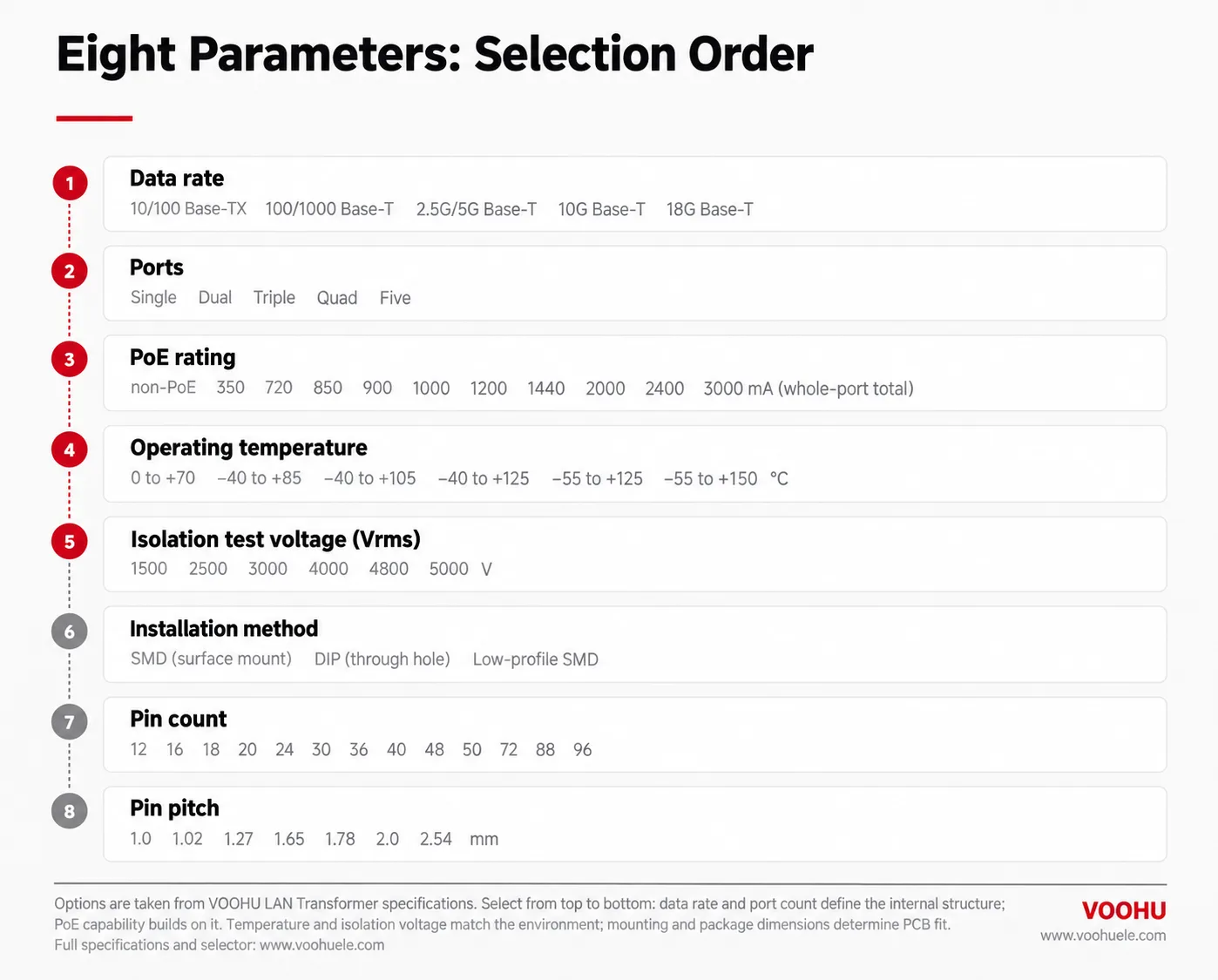
Internal structure: differential pair → pairset → port
Level 1: the differential pair, or signal channel
In the arrangement discussed here, each differential-pair channel consists of one transformer (X'FMR) and one common mode choke (CMC), serving one twisted pair.
Look at the smallest repeated unit in the schematic. Each side has three connections: two differential signal pins and one center tap (CT). Typical names are TD+, TD− and TDCT on the PHY side, and TX+, TX− and TXCT on the cable side. The signal uses the differential pins; the center taps provide access to the winding midpoints.
Level 2: the pairset
Two differential pairs form one PoE current loop, called a pairset.
Why a loop? DC needs a return path. In PoE operation, current leaves through the center tap associated with one pair, travels along that twisted pair to the remote equipment, and returns along a second pair to the other center tap. Two differential pairs, one outgoing path and one return path, complete the circuit.
This is why a PoE current rating may be specified per pairset: the power path involves the complete loop, rather than an isolated winding.
Level 3: the port
For the four-pair Gigabit and higher-speed interfaces discussed here, two pairsets make up one port. Gigabit Ethernet uses all four twisted pairs for data: four differential-pair channels, grouped into two pairsets, connect to one external RJ45 port.
One port = two pairsets = four differential pairs.
This gives a useful pin-count check. A single-port Gigabit transformer with all six connections brought out for each differential pair needs 4 × 6 = 24 pins. That explains the familiar 24-pin package. Applying the same arrangement to two Gigabit ports gives eight differential pairs and 48 pins. Actual packages can differ where extra connections are included, so always check the product pinout.
Data rate: how many signal paths are needed?
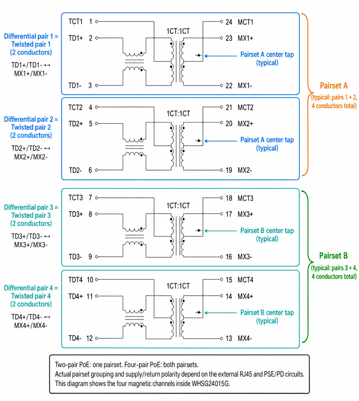
VOOHU's LAN Transformer selector lists five data-rate groups: 10/100 Base-TX, 100/1000 Base-T, 2.5/5G Base-T, 10G Base-T and 18G Base-T.
Once the three structural levels are clear, data-rate selection becomes easier to understand. A 10/100 Base-TX data interface uses two twisted pairs: two differential-pair channels. The four-pair Gigabit and higher-speed interfaces discussed here use four differential-pair channels, which provide two pairsets for four-pair PoE.
Data rate therefore affects more than bandwidth. It also influences the number of internal signal paths, pin count and package size.
That is why a 10/100 design cannot be upgraded to Gigabit simply by adding another component. The other two pairs need complete signal paths, including the magnetic channels, pins and PCB traces. The change requires a suitable component and a revised board design.
Two further points help with selection:
First, match the transformer to the PHY.A higher data-rate rating is not automatically a better choice. A higher-speed part may support lower-speed operation, but compatibility still depends on the PHY requirements, pinout and electrical specifications, while package size and cost also matter.
Second, settle the package early.Many VOOHU 2.5/5G and 10G models use 1.0–1.27 mm pin pitch, but this is not a universal limit: the selector also lists other pitches for particular products. Confirm the specific package before committing the PCB layout.
Port count: how the loops are grouped
VOOHU's LAN Transformer range includes single-, dual-, triple-, quad- and five-port configurations.
A common misunderstanding in multi-port selection concerns power capability:each port has its own rating.
A dual-port Gigabit device contains eight differential-pair channels and four pairsets. Two pairsets serve the first port, and the other two serve the second. Sharing a package does not allow one port to borrow current capability from the other. Adding all four pairset ratings together does not give the capability of a single port.
Keep this distinction in mind for the PoE calculation below: evaluate the rating for each port separately.
Choosing between single-port and multi-port parts usually involves three trade-offs: PCB area, routing density and isolation between ports. Multi-port parts can save board area but concentrate the pins and traces. Separate single-port parts can make it easier to maintain distinct isolation areas where the design requires them.
PoE rating: how to read the current figures
Recall the structure: one pairset consists of two differential pairs forming one current loop. In a four-pair Gigabit port, there are two pairsets.
“Each channel” and “full channels”
When reading a datasheet, establish what the manufacturer means bychannel. In the current-rating example used here:
- each channelmeans the current capability of one pairset, or current loop;
- full channelsmeans the combined capability of the pairsets serving one port.
Consider a dual-port Gigabit device with eight differential-pair channels and four pairsets. If the datasheet specifies 720 mA for each pairset, the two-pairset total for one port is:
720 mA × 2 pairsets = 1440 mA per port.
It is not 2880 mA per port. The four pairsets belong to two separate ports, each with its own 1440 mA capability under this rating convention. Summing every channel in the package is a common way to overstate what one port can carry.
The words “each channel” and “full channels” should not be assumed to have the same meaning in every datasheet. VOOHU's selector uses whole-port PoE current values; confirm the rating basis before converting a datasheet value or comparing manufacturers.
Two practical selection rules
1. Establish the PoE standard and powering arrangement before comparing current.The two-pair powering used by 802.3af/at and the four-pair powering used in 802.3bt (4PPoE) distribute current differently. The same whole-port total does not imply the same load on each current loop. A two-pairset total is relevant only when the powering arrangement uses both pairsets.
2. Treat the current rating as a limit, not a target operating point.Allow margin above the actual peak load. Temperature rise, cable voltage drop and surge conditions all need to be considered.
Frequently asked questions
1. What exactly is a pairset?
A pairset is a PoE current loop formed by two twisted pairs. Current travels out through one pair and returns through the other, using their associated center taps. A per-pairset rating describes that complete loop. Always distinguish it from a per-pair or whole-port rating.
2. Can a 10/100 design become Gigabit by adding another transformer?
No. The data interface must expand from two twisted pairs to four. The additional differential-pair channels need the correct magnetic components, pins and routing, together with a compatible PHY. This requires component selection and PCB changes.
3. Why are many single-port Gigabit transformers 24-pin devices?
Four differential-pair channels, each with two signal pins and one center tap on each side, give 4 × 6 = 24 connections. The pin count follows the internal arrangement; the actual product pinout remains the final reference.
4. What does 720 mA per pairset mean for a dual-port device?
With two rated pairsets in use, the example gives 1440 mA for each port. The two ports remain separate: do not add all four pairsets and claim 2880 mA for one port.
What comes next?
This first part covers three of the eight selection parameters. They form a sequence:data rate establishes the signal paths → port count groups those paths → PoE capability is evaluated within that structure.
The next part will cover the remaining five parameters: operating temperature, isolation test voltage, installation method, pin count and pin pitch.