How to Design a Single Pair Ethernet (SPE) Interface: Magnetics, PoDL and Connectors
How to Design a Single Pair Ethernet (SPE) Interface: Magnetics, PoDL and Connectors
A Single Pair Ethernet (SPE) interface splits the job of the center-tapped LAN transformer in an RJ45 port across several parts: DC-blocking capacitors couple the signal and block DC, a common mode choke (CMC) suppresses common-mode noise, a common-mode termination gives that noise a path to ground, and a low-capacitance ESD device clamps static. When the two ends do not share ground or the product needs galvanic isolation, a small isolation transformer is added. Power over Data Lines (PoDL) enters and leaves the pair through coupling inductors. The connector is chosen by its IEC 63171 mating interface first, then by protection, termination and rating. VOOHU provides 100 Mb/s and 1 Gb/s SPE reference circuits built from VOOHU connector, CMC, transformer and ESD parts with JLSemi PHYs.
This is part 2 of the VOOHU Single Pair Ethernet guide;part 1explains the PHY family, cable reach and the 2026 standards.
Does Single Pair Ethernet need a transformer?
Not always. Use an isolation transformer when the two ends can sit at different ground potentials, for example on cables that run between devices or cabinets, or when the product's safety requirements call for galvanic isolation. Inside one device or on a short link between boards, AC coupling capacitors plus a common mode choke are enough. The isolation rating comes from the transformer and is checked against the product's safety standard.
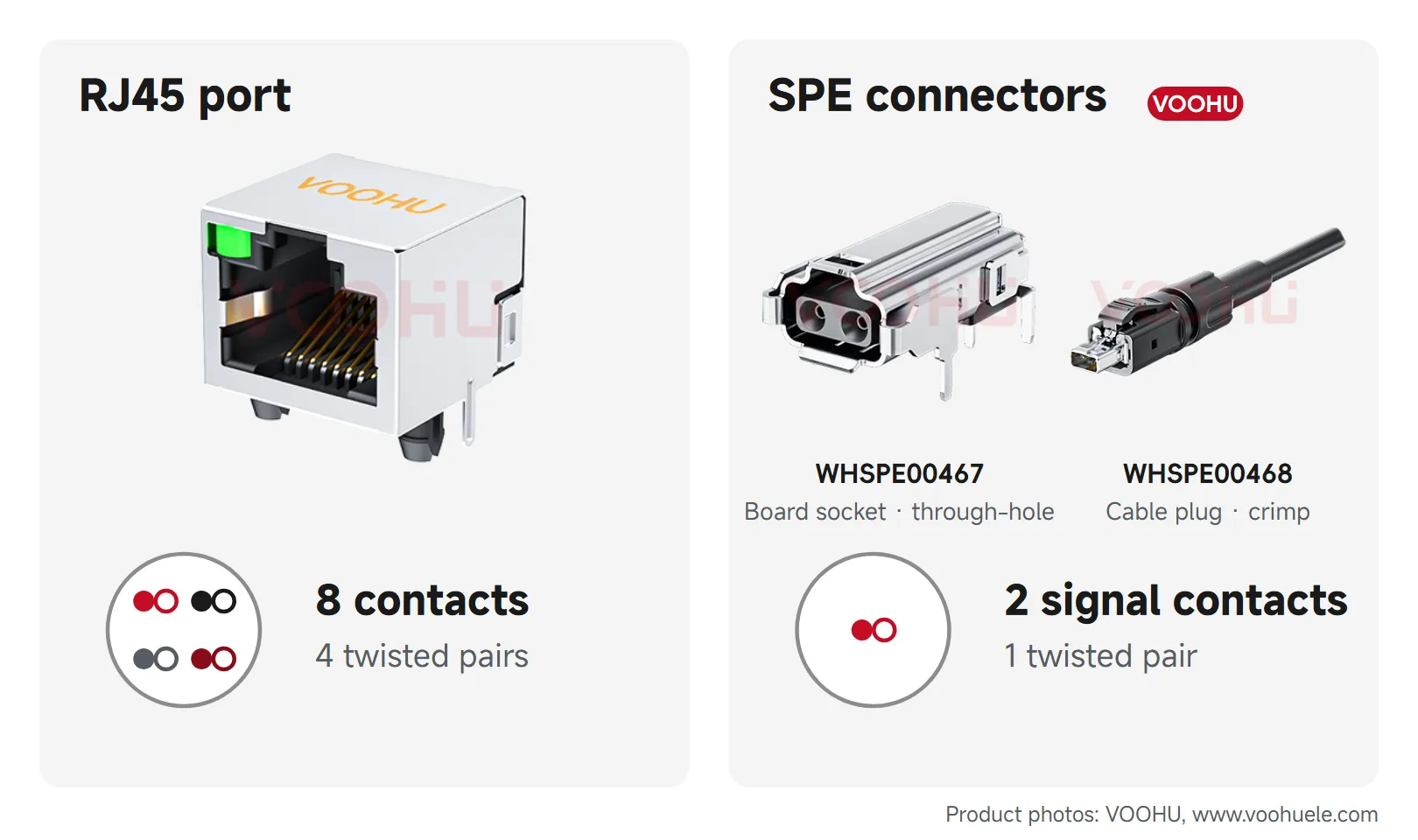
This is a change from RJ45. In a 10/100BASE-TX or 1000BASE-T port, each pair maps to one center-tapped magnetic channel of the LAN transformer, which isolates the two grounds, couples the differential signal and rejects common-mode noise; when PoE is added on a data pair, the current enters and leaves through the center taps.
Which components go between the PHY and the SPE connector?
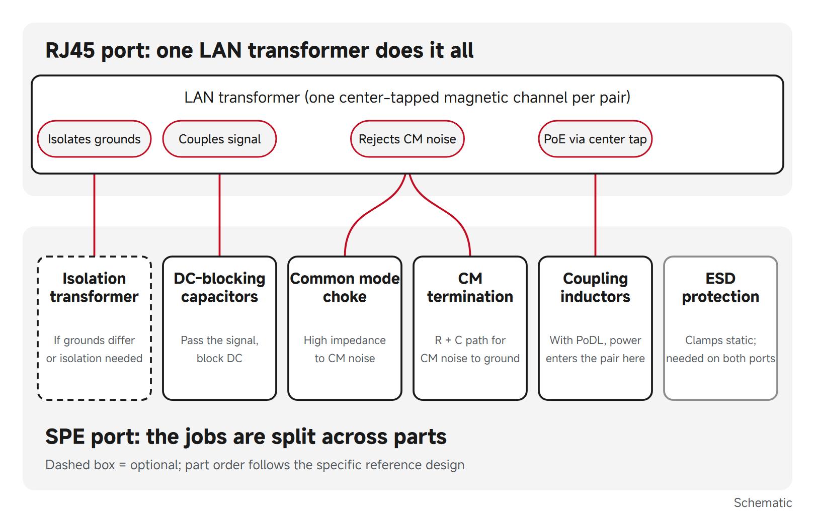
Figure 1: The jobs of an RJ45 LAN transformer and the SPE parts that take them over; the dashed box is optional. Schematic.
- DC-blocking capacitorssit in series with the line, pass the differential signal and block DC.
- Common mode choke (CMC):both wires are wound in the same direction on one core, so the differential signal passes almost unaffected while common-mode noise sees a high impedance.
- Common-mode termination:a resistor and capacitor network gives common-mode noise a return path to ground.
- ESD protection:a low-capacitance device clamps static; low parasitic capacitance keeps it from loading the signal.
- Isolation transformer (optional):added when the grounds can differ or the product requires isolation.
TheVOOHU JL31X1 SPE port design referenceis a non-isolated example: a common mode choke, common-mode termination, DC-blocking capacitors and ESD protection sit between the PHY and the connector.
What does the VOOHU SPE reference circuit use?
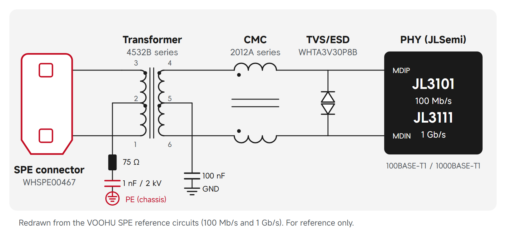
Figure 2: VOOHU SPE standard reference circuit, redrawn from the 100 Mb/s and 1 Gb/s design PDFs. For reference only.
TheVOOHU SPE solution pageprovides 100 Mb/s and 1 Gb/s standard circuit designs. Both are isolated and use a JLSemi PHY: the JL3101 for 100 Mb/s and the JL3111 for 1 Gb/s. VOOHU is an authorized distributor of JLSemi. From the PHY to the connector, the parts are:
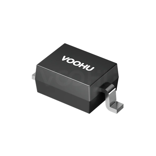
- TVS/ESD:WHTA3V30P8B, a low-capacitance ESD protection device in SOD-323;
- Common mode choke: 2012 size, from the2012A series;
- Transformer: a 4532-size SMD transformer from the4532B series, for isolation and impedance matching;
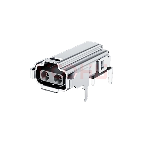
- SPE connector: theWHSPE00467board socket.
On the PHY side, the transformer center tap goes to GND through 100 nF to filter high-frequency noise. On the cable side, 75 Ω and 1 nF to chassis ground give common-mode current a return path and improve EMI. Rate the 1 nF capacitor for 2 kV or more; a 1206 SMD ceramic capacitor or a high-voltage ceramic disc capacitor with wide lead spacing is recommended.
The JL3111 complies with IEEE 802.3bw (100BASE-T1) and IEEE 802.3bp (1000BASE-T1).
Data sources: VOOHU 10/100M and 100/1000M Single Pair Ethernet (SPE) Standard Circuit Design PDFs on the SPE solution page; WHTA3V30P8B datasheet, revision March 1, 2022.
How does Power over Data Lines (PoDL) work?
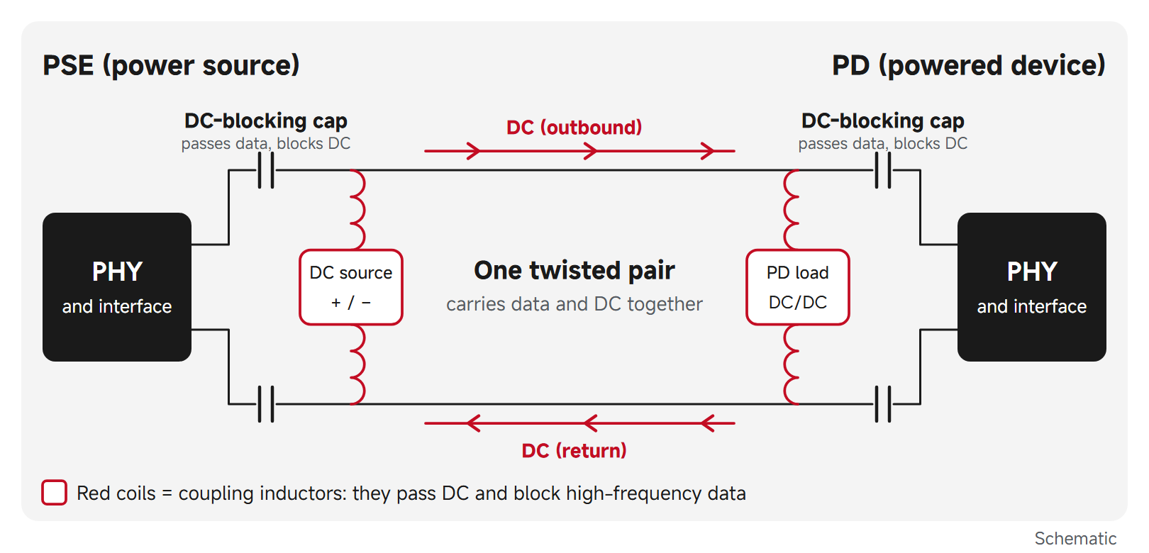
Figure 3: PoDL power loop: coupling inductors put DC on the pair and take it off; DC-blocking capacitors keep it out of the PHY. Schematic.
A single pair has no second pair to carry the return current, so PoDL applies DC across the two conductors of the same pair. The power sourcing equipment (PSE) couples DC onto the pair through inductors and the powered device (PD) takes it off through inductors, while series DC-blocking capacitors keep the DC out of the transformer and PHY. The inductors present a high impedance to the data, so power and data share the pair without interfering.
Before applying power, the PSE runs detection to confirm that a PD is connected. The power class can be read over SCCP (serial communication classification protocol), or skipped when the PD is known in advance. IEEE 802.3bu defines classes 0 to 9 at nominal 12 V, 24 V and 48 V, with 0.5 W to 50 W at the PD; IEEE 802.3cg adds classes 10 to 15, with PSE output voltages of 20 V to 30 V (classes 10 to 12, for 24 V systems) and 50 V to 58 V (classes 13 to 15), and 1.23 W to 52 W at the PD.
Data sources: IEEE 802.3bu and 802.3cg task force tutorial and proposal materials; the formal class tables are in the standard.
- Coupling inductors:check saturation current and DC resistance against the supply current; the inductors also affect return loss and mode conversion. They are a different part from a signal CMC and the two are not interchangeable.
- DC-blocking capacitors:rate them for the supply voltage and its transients.
- Connectors:check the current rating and temperature rise against the PoDL current; on a multidrop bus, use the maximum current of the whole segment.
Which SPE connector standard: IEC 63171-1, -2, -4, -5, -6 or -7?
Industrial SPE mating interfaces are defined in the IEC 63171 series, and both ends of a link must use the same part:
| Part | Form | Key points |
|---|---|---|
| IEC 63171-1:2024 | LC style, 2 contacts | 600 MHz; 2.0 A at 60 °C |
| IEC 63171-2:2021 | 2 contacts | 600 MHz |
| IEC 63171-4:2022 | Multimedia connector, up to 8 contacts | Optional PoDL |
| IEC 63171-5:2022 | M8 / M12 circular, 2 contacts | IP65 / IP67; up to 4 A |
| IEC 63171-6:2021 | 2 data contacts, or 4 for data and power; shielded | 600 MHz |
| IEC 63171-7:2023 | Circular, up to 7 contacts, data and power | M12 / P12 / C12 locking |
Data sources: IEC webstore listings for each part of IEC 63171.
Once the mating interface is fixed, check four more things: protection (inside equipment or a cabinet, or IP65/IP67 in the field); termination (through-hole or SMD on the board, crimp on the cable); whether the current and voltage ratings cover the PoDL class; and whether you need shielding.
Note: Multiplying a connector's rated current by its rated voltage does not give the system's power capability. The deliverable power depends on the PoDL class, cable voltage drop, contact resistance and temperature rise.
Which VOOHU parts fit an SPE port?
| Position | Part | VOOHU part number or series |
|---|---|---|
| Board connector | 2-pin socket, through-hole, 4 A, 60 V | WHSPE00467 |
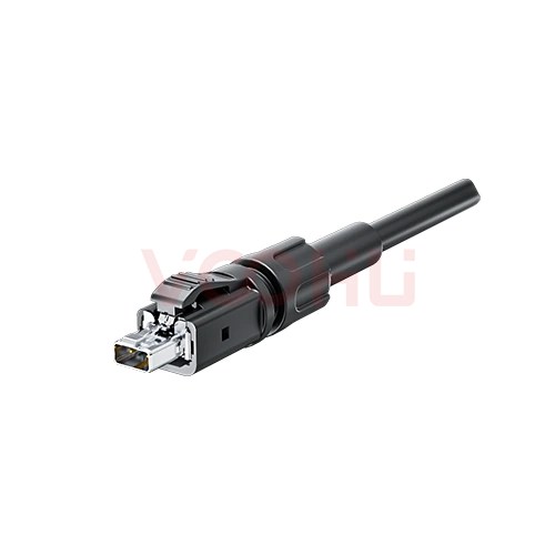
| Cable connector | 2-pin plug, crimp, 4 A, 60 V | WHSPE00468 |
| ESD protection | Low capacitance, SOD-323 | WHTA3V30P8B |
| Common-mode suppression | Common mode choke, 2012 size | 2012A series |
| Isolation and impedance matching | SMD transformer, 4532 size | 4532B series |
| PHY | 100 Mb/s or 1 Gb/s SPE PHY | JLSemi JL3101 / JL3111 |
Before choosing the WHSPE00467 and WHSPE00468, check their mating drawings against the interface of the device at the other end; for the crimp plug, take wire gauge, strip length and crimp tool from the contact data. Compare both in theSPE connector selector. TheSPE connector selection guidecovers crimp, mating and PoDL harness checks.
FAQ
Q1: Does Single Pair Ethernet need a transformer, or are coupling capacitors enough?
Coupling capacitors plus a common mode choke are enough when both ends share ground and no isolation is required. Add a small isolation transformer when the grounds can differ or the product needs galvanic isolation; the VOOHU 100 Mb/s and 1 Gb/s reference circuits use a 4532 SMD transformer for isolation.
Q2: Can a 4 A, 60 V SPE connector deliver 240 W over PoDL?
No. The ratings are limits for the connector, not the system's power capability. The power you can deliver depends on the PoDL class, cable voltage drop, contact resistance and temperature rise; on a multidrop bus, the bus current passes through every connector, so check the maximum current.
Q3: Can existing cable be reused for Single Pair Ethernet?
Only after it has been qualified against the link segment requirements of the target PHY. Reach and the number of inline connectors differ from one PHY to another, so test the installed cable before reusing it.
Q4: Where can I download the VOOHU SPE reference circuits?
On theVOOHU SPE solution page, as 100 Mb/s and 1 Gb/s PDFs. Datasheets and 3D models for the WHSPE00467 and WHSPE00468 connectors are on their product pages.
Get your SPE port checked
Send your PHY, isolation and PoDL needs and the mating interface through thesample and support request form. Our FAE team can suggest the SPE connector, common mode choke, transformer and ESD parts for your port and check the circuit against the reference design. Samples are available for evaluation, and selected parts are free of charge. Our FAE team will be glad to confirm the options for your project.
VOOHU supplies RJ45, SFP and SPE connectors, LAN and PoE transformers, common mode chokes and TVS/ESD protection devices from Suzhou, China, to more than 1,500 customers.