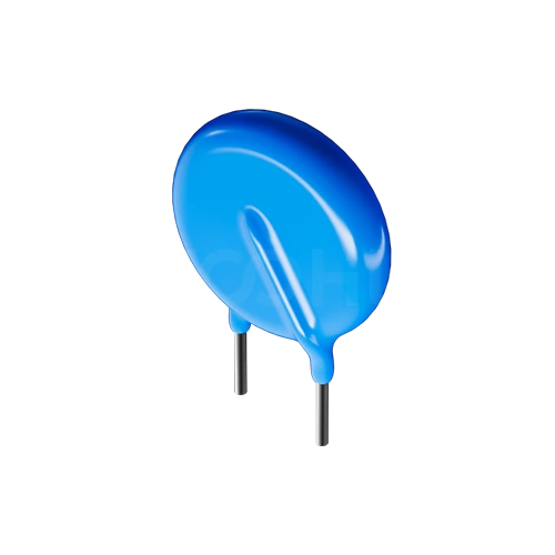
How to Test a Varistor (MOV): What a Multimeter Can and Cannot Tell You
To test a metal oxide varistor (MOV), remove power, discharge the circuit and inspect the part for cracks, burn marks or a bulging coating. Then lift one lead and measure it with a multimeter on a high resistance range. A healthy MOV reads very high resistance in both directions, often beyond the meter's range; a reading near zero ohms means it has failed short. A multimeter cannot prove the varistor still works, because an MOV only starts to conduct near its varistor voltage, which is defined at a small stated DC current, usually 1 mA. Checking that voltage needs a current-limited DC supply that can exceed it. Clamping voltage and remaining surge capability cannot be verified on the bench without a surge generator, so an MOV that has absorbed a severe surge is usually replaced rather than tested.
What can a multimeter tell you about a varistor?
A multimeter catches the most common hard failure, a short circuit, and not much else. The reason is the shape of the varistor's voltage-current curve: far below the varistor voltage the part draws almost no current, and the few volts a meter applies on its resistance range sit deep in that region.
| Test | Tool | What a healthy part shows | What it proves | What it misses |
|---|---|---|---|---|
| Visual inspection | Eyes, magnifier | Intact coating, no cracks or discoloration | Obvious thermal or mechanical damage | Internal degradation |
| Resistance | Multimeter, highest ohms range | Very high or over-range, both polarities | Not shorted | Drift in varistor voltage, lost surge capability |
| Diode test | Multimeter diode mode | Over-range in both directions | Not shorted | Same as resistance test |
| Capacitance | Multimeter or LCR meter | Close to the typical value in the datasheet, if one is given | Disc is still connected internally | Voltage and surge behavior |
| Varistor voltage | Current-limited DC supply, or a tester with current readout | Within the datasheet tolerance at the stated current | Conduction threshold is still in spec | Clamping voltage, surge life |
| Clamping voltage | Surge generator with stated waveform | At or below the datasheet value | Surge behavior at that current | Long-term aging |
One caution: low-voltage multilayer varistors have thresholds much closer to a meter's test voltage than disc MOVs for mains use. On those parts even the resistance reading can be misleading, so rely on the datasheet test method.
How do you measure varistor voltage at 1 mA?
Varistor voltage, sometimes written V1mA or Vn, is the voltage across the part while a small stated DC current flows through it. Most datasheets use 1 mA; check yours, because some parts use a different current.
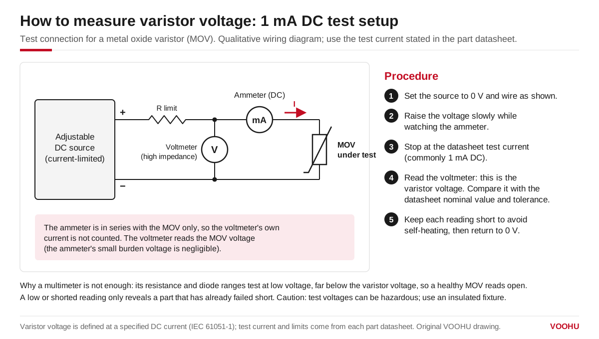
Varistor voltage is the voltage across the MOV at the datasheet test current (commonly 1 mA DC); a multimeter's resistance range cannot measure it.
- Remove the varistor from the circuit, or at least lift one lead.
- Connect an adjustable, current-limited DC supply through a series resistor. Put a milliammeter in series with the varistor and a voltmeter across the milliammeter and varistor together, so the milliammeter counts only the varistor current. An insulation or hipot tester that displays current can do the same job.
- Start from 0 V, set the current limit to the datasheet test current and raise the voltage slowly until that current flows.
- Read the voltage quickly, within a second or two, then switch off. At 1 mA and several hundred volts the dissipation can approach or exceed the steady-state power rating of a small disc, so keep the test short.
- Compare the reading with the nominal value and tolerance in the datasheet.
Suppose a datasheet specifies a varistor voltage of 100 V ±10% at 1 mA DC. An acceptable reading is then between 90 V and 110 V. A reading of, say, 80 V would place the part outside its tolerance even though a multimeter would still show it as open.
Mains-rated varistors have varistor voltages in the hundreds of volts. Treat this as a high-voltage test: use insulated leads, keep hands clear while the supply is on, and discharge any capacitance in the circuit before touching it.
What does a drift in varistor voltage mean?
Each surge slightly degrades the zinc oxide ceramic. Over many events the varistor voltage drifts downward, leakage current at normal operating voltage rises, and the part runs warmer in normal service. Left in place, a degraded MOV can eventually fail short and overheat, which is why a mains varistor belongs behind a fuse or next to a thermal cut-out.
Many varistor datasheets define end of life in their surge-rating tests as a shift in varistor voltage beyond ±10% of the initial value. Check the criterion your part's datasheet uses. If you have a reading from when the part was new, the change is more informative than the absolute value.
What are the visual signs of a failed MOV?
Thermal failure usually leaves marks you can see before you measure anything.
- Cracks or chips in the disc or its coating
- A bulged, blistered or peeling coating
- Brown or black discoloration on the body or the board around it
- Melted or reflowed solder joints on the leads
- An open fuse or thermal fuse upstream of the varistor
Any of these is reason enough to replace the part. A varistor that looks damaged but still reads open on a multimeter has not passed a test; the meter simply cannot see the damage.
Why test the varistor out of circuit?
In circuit, the varistor is in parallel with other parts. On an AC input that usually means an X capacitor, a bleeder resistor and, after the rectifier, a bulk capacitor. A resistance reading then shows the parallel combination, and a capacitance reading includes the X capacitor. Lift at least one lead before measuring. Discharge the input capacitors first, because a charged bulk capacitor can damage the meter and the person holding it.
What can a bench test not tell you?
Two ratings matter most in service and neither can be checked with a multimeter or a DC supply.
- Clamping voltage.This is the voltage across the part while it diverts a stated surge current, typically with a standard surge waveform such as 8/20 µs, and it is substantially higher than the varistor voltage. VOOHU lists its WHM0082VAmetal oxide varistor, aD14 disc, with a 135 V clamping voltage; see the datasheet for the surge current at which that figure applies.
- Remaining surge and energy capability.A varistor that passes every bench test may already have used much of its rated surge life. Only the history of surges it has seen, compared against the derating curve in the datasheet, gives an indication.
For a design decision rather than a repair, select against the datasheet ratings and plan the failure mode, instead of relying on incoming tests.
产品WHM0082VA
FAQ
Q1: Can you test a varistor with the diode setting on a multimeter?
You can use it as a short-circuit check. A healthy varistor reads over-range in both directions on diode test. Unlike a diode, it shows no forward voltage drop in either direction, because a metal oxide varistor is a symmetrical, voltage-dependent resistor rather than a PN junction.
Q2: Does a varistor have polarity?
No. A metal oxide varistor has a symmetrical voltage-current characteristic, so it clamps positive and negative surges the same way and can be fitted either way around. Polarity only matters for some combined protection parts, so follow the datasheet if the part has a marked lead.
Q3: Should I replace a varistor that tests good after a large surge?
In most cases, yes. A multimeter pass only shows the part is not shorted, and even a varistor voltage within tolerance does not show how much surge life remains. If the upstream fuse or thermal protection operated, or the part shows any discoloration or cracking, replace it with a part of the same or higher rating.