
Shielded vs Unshielded RJ45 Connector: When Does a PCB Jack Need a Shield, and How Should It Be Grounded?
Shielded vs Unshielded RJ45 Connector: When Does a PCB Jack Need a Shield, and How Should It Be Grounded?
Short answer.Use a shielded RJ45 connector when the product will be cabled with shielded twisted pair (F/UTP, S/FTP and similar), when it sits in a metal enclosure that must meet tight emission or immunity limits, or when the port faces a noisy industrial environment. Otherwise an unshielded jack is usually enough. The metal shell does not help by itself: it only works when it has a short, low-impedance path to chassis ground, through solder tabs to a chassis-ground area on the PCB, spring fingers to the front panel, or both. A shielded jack with a floating shell can perform worse than an unshielded one, so decide the grounding scheme at the same time as you choose the part.
What is the difference between a shielded and an unshielded RJ45 jack?
Both carry the same eight contacts and the same pinout. The difference is the metal around them and where that metal connects.
| Feature | Unshielded RJ45 jack | Shielded RJ45 jack |
|---|---|---|
| Housing | Plastic only | Plastic insert inside a metal shell |
| Contact with a shielded plug | None; the plug's metal shell touches plastic | The plug shell touches the jack shell, so the cable shield continues into the product |
| Ground connection | Not applicable | Shell solder tabs to PCB chassis ground; on many parts, spring fingers to the panel |
| Effect on emissions and immunity | Relies on cable twist, magnetics and board layout | Adds a shield path that diverts common-mode noise to chassis, if grounded well |
| Board and panel impact | Simpler footprint and panel cutout | Extra ground pads; the panel opening may need to suit spring fingers |
The pair balance in the cable, the LAN transformer and the common-mode filtering on the board do most of the noise work in either case. The shield adds a second line of defense for common-mode currents on the cable.
When should you choose a shielded RJ45 connector?
| Situation | Suggested jack | Why |
|---|---|---|
| Product will be used with shielded cable (F/UTP, U/FTP, S/FTP) | Shielded | ISO/IEC 11801 and ANSI/TIA-568 screened cabling relies on shield continuity at every connection; an unshielded jack breaks it |
| Metal enclosure with demanding EMC targets | Shielded, with panel contact | The shell and panel can form one continuous chassis surface around the opening |
| Industrial cabinets, drives, motors, long cable runs near power wiring | Shielded | Common-mode noise coupled onto the cable can be returned to chassis at the entry point |
| Office or consumer product cabled with U/UTP, plastic enclosure | Unshielded is usually fine | No cable shield to terminate and often no chassis to terminate it to |
| Plastic enclosure but shielded cable is expected | Shielded, with a planned ground reference | See the plastic-enclosure note under grounding below |
If you are not sure what cable the customer will use, a shielded jack with a defined ground path covers both cases: it works with unshielded cable too, as the mating table further down shows.
Shield tabs vs EMI fingers: what the two specifications mean
Shielded jacks reach chassis ground in two ways, and parts differ in which they offer.
- Shield tabsare metal legs on the shell that are soldered into the PCB, normally into a chassis-ground copper area.
- EMI fingers(also called EMI springs) are spring contacts around the jack opening that press against the inside of a conductive front panel. Some parts use a conductive EMI gasket for the same job.
On the VOOHURJ45 PCB jackspage, the selection table lists both as separate fields: "Shield Tabs" (YES/NO) and "EMI / Gasket" (YES/NO). Parts are listed with both, with shield tabs only, and with neither. All three combinations appear among jacks with and without integrated magnetics, and among both through-hole (DIP) and surface-mount (SMD) parts. Two examples:
| Part number | Type | Shield Tabs | EMI / Gasket |
|---|---|---|---|
| WH56A3188C041101 | 90°, 1×1, tab up, no integrated magnetics, DIP | YES | YES |
| SYT561188IWD1DY1027 | 90°, 1×1, tab up, no integrated magnetics, no LED, DIP, all-plastic housing | NO | NO |
The two versions can sit in the same series. In the SYT561188 series, SYT561188AB1A1DB4 and SYT561188HWA1DB4 have a nickel-plated brass shield shell and two through-hole shield pins in the PCB layout, while SYT561188IWD1DY1027 is all plastic, with only two plastic locating posts and no shield pins.
Treat these fields as a first filter. The table does not define them in detail, so confirm on the part drawing what the shell, its ground pins and any fingers or gasket look like. Shell material and plating, the number and position of fingers, the number of ground pins and their hole sizes are part-specific: see the datasheet.
Choose EMI fingers when the jack sits behind a metal panel and the shell should bond to it all around the opening. Without fingers, the shell reaches chassis only through its PCB tabs, so the board-to-chassis connection near the connector matters more.
How to ground a shielded RJ45 jack on the PCB
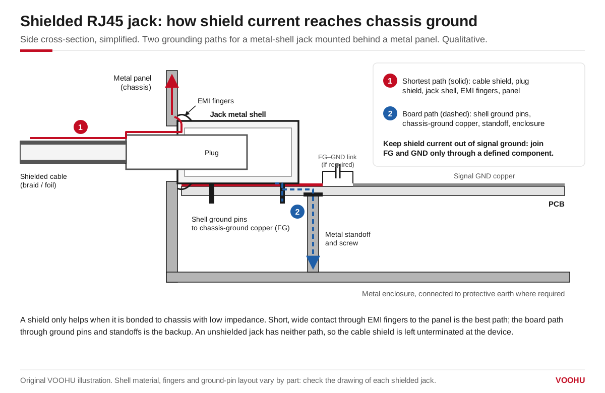
A shielded RJ45 only helps when its shell is bonded to chassis with low impedance, ideally through EMI fingers to the panel, with the board path as backup.
The aim is a short path from the cable shield to chassis at the point where the cable enters, so noise currents never cross the circuit.
- Create a chassis-ground area under the jack.Solder the shell tabs into copper that is separate from the signal ground and connected to the metal enclosure by a screw, standoff or panel contact close to the connector.
- Keep the isolation boundary.IEEE 802.3 requires the cable-side (MDI) leads to be electrically isolated from the device circuits, including frame ground; a 1500 V rms, 60 s withstand test is one of the accepted ways to verify it. On the PCB, that means the cable-side copper (the transformer's cable-side pins, center-tap termination and any traces to the jack contacts) stays spaced away from both the chassis-ground area and the PHY-side circuitry. Only the transformer and parts designed to bridge the barrier, such as high-voltage capacitors, should cross it, and no signal traces should run through the gaps.
- Decide how chassis and signal ground meet.Common choices are a direct bond at one defined point near the connector, or a connection through a high-voltage capacitor. Many designs also return the cable-side center-tap termination (often called Bob Smith termination) to the same chassis-ground area through a high-voltage capacitor. Component values and ratings depend on your EMC and safety targets; settle them with your EMC engineer.
- Do not leave the shell floating.An unconnected shell can pick up and re-radiate noise instead of draining it.
Plastic enclosures.With no metal chassis, there is no chassis ground in the usual sense. The shell is typically tied to a defined board reference, often through a capacitor, and the layout needs a planned discharge path for ESD. Our guide toEthernet PCB design for plastic enclosurescovers that case.
Does a shielded jack work with unshielded cable, and the other way around?
Yes, both combinations plug in and pass data. What changes is whether the shield path is continuous.
| Plug / cable | Jack | Result |
|---|---|---|
| Unshielded plug, U/UTP cable | Unshielded jack | Normal UTP link |
| Unshielded plug, U/UTP cable | Shielded jack | Works; the jack shell still grounds to the panel, but there is no cable shield to terminate |
| Shielded plug, F/UTP or S/FTP cable | Shielded jack | Shield continues from cable to chassis; the intended combination |
| Shielded plug, F/UTP or S/FTP cable | Unshielded jack | Links, but the cable shield ends unconnected at this end and can act as an antenna |
Layout and assembly checks for shielded RJ45 jacks
| Check | What to look for |
|---|---|
| Ground pads | Shell tabs land on chassis-ground copper, not on signal ground |
| Board-to-chassis bond | A screw or standoff near the connector, with a short connection to the chassis-ground area |
| Panel contact | With EMI fingers fitted, the fingers press on bare conductive metal, not paint or anodizing |
| Gap integrity | No signal traces crossing the boundary between chassis ground and signal ground |
| Stacked and multi-port jacks | Every port's shell section and every ground tab is connected |
| Assembled unit | Shell-to-chassis continuity measured in the final enclosure, before and after repeated mating |
Spring contact and panel fit depend on the real enclosure, soverify shield and spring contact in the real panelduring the prototype stage rather than on a bare board.
FAQ
Q1: Do I need a shielded RJ45 connector for Cat6?
Not necessarily. Cat6 describes cable and connector transmission performance, and Cat6 is available as both unshielded (U/UTP) and shielded cable. Choose a shielded jack when the installation uses shielded cable or the product needs the extra EMC margin. For the category rating of a specific jack, see the datasheet.
Q2: Should the RJ45 shield connect to signal ground or chassis ground?
Connect the shell to chassis ground, close to where the cable enters. Signal ground and chassis ground then meet at one defined point, either directly or through a high-voltage capacitor, chosen to suit the product's EMC and safety requirements. Avoid tying the shell straight into signal ground under the PHY.
Q3: Can a shielded RJ45 jack replace an unshielded one on the same footprint?
Usually not without a layout change. The shielded part adds shell ground tabs, and its body, hole pattern and panel cutout can differ. Check the drawings of both parts pin by pin, add the chassis-ground pads and confirm the panel opening before switching.