




Standoff voltage
The highest voltage the device tolerates without conducting. Set it above the normal working voltage including ripple, or the part leaks in service.

Gamme de composants de protection
TVS diodes absorb surge energy; ESD devices clamp fast static discharges with very low capacitance. Both clamp, but they are sized for different events. Start from what you are protecting against, then match standoff voltage, clamping voltage and capacitance to the port.
Recherche et sélection de références
Le tableau utilise les fiches produits actuelles du site anglophone, les critères de sélection publiés et les liens vers les fichiers techniques propres à chaque référence.
* Colonnes Image et Référence figées · faites glisser horizontalement pour consulter toutes les caractéristiques
| Image | Fiche technique | Comparer | Téléchargements |
Polarité
|
Vrwm/V
|
Vesd air / Vesd contact
|
Cj/pF
|
Boîtier
|
Température de fonctionnement
|
Échantillon |
|---|
| Image | Référence | Fiche technique | Comparer | Téléchargements | Polarité | Vrwm/V | Vesd air / Vesd contact | Cj/pF | Boîtier | Température de fonctionnement | Échantillon |
|---|---|---|---|---|---|---|---|---|---|---|---|
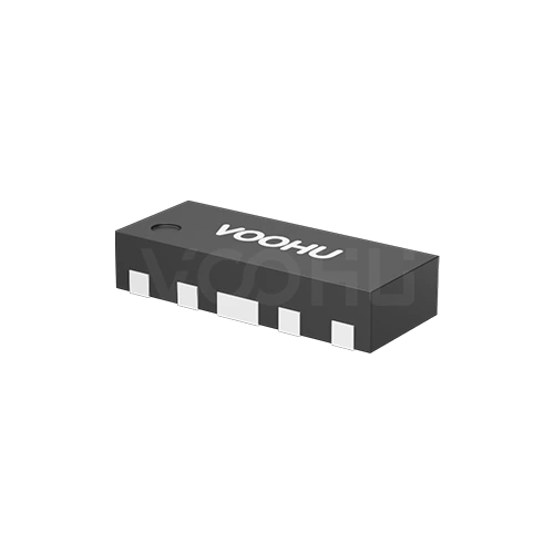 |
WHALD03G4U | SPEC | ESD | 3.3 | ±15KV/±12KV | 0.3 | DFN2510-10L | -40 °C à 125 °C |
|
||
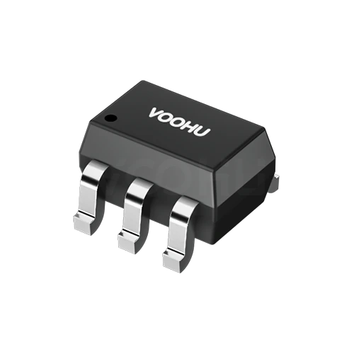 |
WHTA5V01P2C | SPEC | ESD | 5 | ±20KV/±20KV | 1.2 | SOT-363 | -40 °C à 125 °C |
|
||
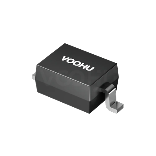 |
WHTA3V30P8B | SPEC | ESD | 3.3 | ±30KV/±30KV | 0.8 | SOD323 | -40 °C à 125 °C |
|
Élargissez les filtres sélectionnés ou effacez la recherche en cours.
By polarity
Polarity follows the signal: unidirectional for DC rails, bidirectional for AC and differential lines.
Comment sélectionner
Threat first, then polarity, then the voltage window, then capacitance.
Surge energy from lightning or switching needs a TVS. Fast human-body or contact discharge on a data port needs a low capacitance ESD device.
Unidirectional suits single-polarity DC rails. Bidirectional suits AC lines and differential pairs that swing both sides of ground.
Standoff voltage above the highest normal working voltage, clamping voltage below what the protected device survives. Both have to hold.
On high speed lines, capacitance decides whether the protection is usable. Measure the eye diagram and return loss after fitting.
Parameters
Standoff and clamping voltage form a window that both has to fit inside.
The highest voltage the device tolerates without conducting. Set it above the normal working voltage including ripple, or the part leaks in service.
Where conduction begins, measured at a small stated test current. It sits above the standoff figure and below the clamping voltage.
The voltage across the device while it diverts a stated peak current. This is what the protected circuit actually sees, so compare at the same current.
Energy handling at a stated waveform, commonly 8 by 20 or 10 by 1000 microseconds. The waveform must match or the figures do not compare.
The load the device places on the line. Low capacitance parts exist specifically so high speed signals are not degraded by the protection.
Unidirectional conducts hard in one direction only. Bidirectional behaves symmetrically, which is required where the signal swings both ways.
Comparer
Energy handling, response speed and capacitance separate the choices.
Revenir au sélecteur ↑| Polarité | Références | Vrwm/V | Vesd air / Vesd contact | Cj/pF | Boîtier | Température de fonctionnement | Action |
|---|---|---|---|---|---|---|---|
| TVS bidirectionnelle | 1 | 58 | - | - | DO-214AB | -60 °C à 150 °C | Filtrer → |
| ESD | 3 | 3.3, 5 | ±15KV/±12KV, ±20KV/±20KV, ±30KV/±30KV | 0.3, 0.8, 1.2 | SOD323, SOT-363, DFN2510-10L | -40 °C à 125 °C | Filtrer → |
| ESD bidirectionnelle | 1 | 30 | ±30KV/±30KV | 0.9 | SOT-23 | -40 °C à 125 °C | Filtrer → |
Analyse de l’application
Confirm the port type, the standard to be met and the signal speed on that line.
Documents
Datasheets carry the clamping curve, pulse waveform conditions and capacitance.
Affichage de jeux de fichiers disponibles représentatifs. Recherchez un SKU précis.
Le contenu produit publié par VOOHU est vérifié par son équipe technique. Les caractéristiques, les téléchargements et les informations d’assistance technique sont associés à des références précises afin que vous puissiez les vérifier avant de demander des échantillons ou un devis.
Présentation de la catégorie
Two decisions cover most of this category: which technology matches the threat, and whether the part needs to be unidirectional or bidirectional.
Discuter d’une nouvelle conception
Contacter l’équipe FAE pour une évaluation de remplacement.
Vous avez déjà une référence ? Demander des échantillons ou un devis.
A TVS diode is sized for surge energy from lightning coupling or heavy switching, rated in peak pulse power at a defined waveform. An ESD device is sized for fast, low energy static discharge and built for very low capacitance, so it can sit on a high speed line. Sizing one against the other threat gives the wrong part.
A unidirectional device conducts hard one way and blocks the other, which suits a DC rail that never goes negative. A bidirectional device is symmetric, which AC lines, differential pairs and buses swinging both sides of ground require. Fit a unidirectional part there and it conducts on the negative half.
The device sits in parallel with the signal, so its capacitance is a load the line has to drive. On a high speed pair, a few picofarads visibly degrades the eye and raises return loss. That is why low capacitance ESD parts are a separate category, and why the eye should be measured with the part fitted.
FAQ
Answers cover TVS against ESD, polarity choice, capacitance and placement.
A TVS diode is sized for surge energy from lightning coupling or heavy switching, rated in peak pulse power at a defined waveform. An ESD device handles fast, low energy static discharge and is built for very low capacitance so it can sit on a high speed line. Both clamp, but they are sized against different events.
Whenever the protected line swings both sides of ground: AC lines, differential pairs and most buses. A unidirectional part conducts hard on the negative half cycle and corrupts the signal. Unidirectional parts suit DC rails that never go negative in normal operation.
Above the highest voltage the line reaches in normal service, including ripple and any transients that are not faults. Too low and the part leaks or conducts during operation. Then check the clamping voltage at your actual surge current still sits below what the protected device survives.
The device sits in parallel with the signal, so its capacitance loads the line. On a high speed pair even a few picofarads visibly degrades the eye and raises return loss. That is why low capacitance ESD parts exist as a separate category, and why you should measure the eye with the part fitted.
As close to the connector as the layout allows, so the discharge is diverted before it reaches the rest of the board, with a short wide path to ground. The signal should not pass the protected chip first and then reach the device. Stray inductance in the ground path adds overshoot.
Only if its capacitance is low enough for the data rate. A general purpose TVS sized for surge energy usually has capacitance high enough to degrade a fast link noticeably. Check the capacitance against your line, and if in doubt measure the eye diagram both ways.
Often yes. Magnetics provide isolation and some common mode rejection but are not a substitute for a clamp against fast transients. Whether additional protection is needed depends on the standard you must meet and on your layout, so confirm against the requirement rather than assuming.
With a complete part number, send the part number, quantity, delivery region and the date you need it. If you are still selecting, send the port type, the normal working voltage, the standard and level you must meet and the data rate on that line.
Assistance technique
Envoyez la référence candidate et la condition à examiner. Vous pourrez demander des échantillons une fois la sélection précisée ; les questions commerciales peuvent être abordées au cours du même échange technique.
Indiquez la révision du document
Température, tension d’isolement et conditions de courant PoE prises comme référence
Nombre de broches, pas et espacement entre les rangées de broches
Pour faciliter la priorisation des échantillons et de l’évaluation
Date à laquelle vous avez besoin de références candidates et d’un comparatif des différences
L’analyse technique identifie les références candidates et explique les différences.
Issues du sélecteur ou de l’analyse technique
Prototypage / présérie / production
Précisez séparément les délais des échantillons et de la production
Documents de conformité, déclarations de matières ou rapports de tiers
La quantité d’échantillons, le délai et le coût dépendent de la phase du projet et de la référence. L’équipe commerciale répond les jours ouvrés.




