




Standoff voltage
The highest voltage the device tolerates without conducting. Set it above the normal working voltage including ripple, or the part leaks in service.

保護部品
ESD devices clamp fast static discharge while adding as little capacitance as possible, which is what a USB, Ethernet or HDMI port needs. Place them close to the connector with a short path to ground, then verify the eye diagram on the real link.
型番検索・選定
この表では、海外サイトの現行製品データ、公開済みの選定項目、型番別の技術資料リンクを使用しています。
※画像列と型番列は固定されています。横にドラッグしてすべての仕様を確認できます
| 画像 | データシート | 比較 | ダウンロード |
極性
|
Vrwm/V
|
Vesd 気中放電/接触放電
|
Cj(pF)
|
パッケージ
|
動作温度
|
サンプル |
|---|
| 画像 | 型番 | データシート | 比較 | ダウンロード | 極性 | Vrwm/V | Vesd 気中放電/接触放電 | Cj(pF) | パッケージ | 動作温度 | サンプル |
|---|---|---|---|---|---|---|---|---|---|---|---|
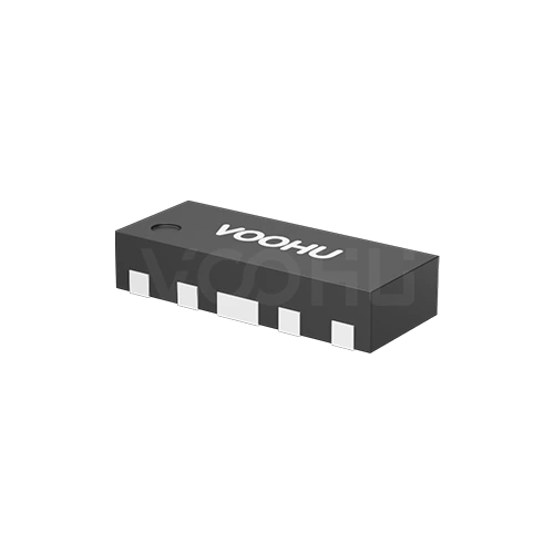 |
WHALD03G4U | SPEC | ESD | 3.3 | ±15KV/±12KV | 0.3 | DFN2510-10L | -40~125°C |
|
||
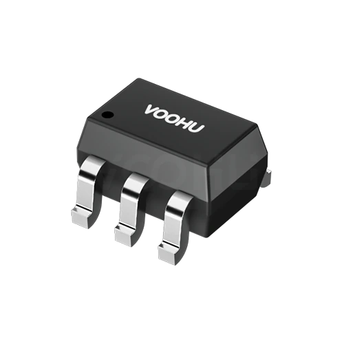 |
WHTA5V01P2C | SPEC | ESD | 5 | ±20KV/±20KV | 1.2 | SOT-363 | -40~125°C |
|
||
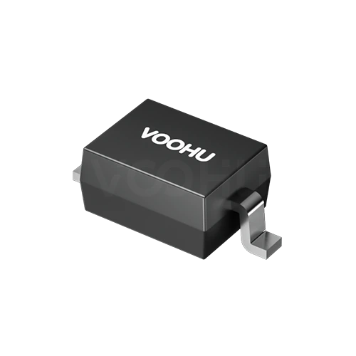 |
WHTA3V30P8B | SPEC | ESD | 3.3 | ±30KV/±30KV | 0.8 | SOD323 | -40~125°C |
|
選択した条件を広げるか、現在の検索条件をクリアしてください。
By polarity
Polarity follows the signal: unidirectional for DC rails, bidirectional for AC and differential lines.
選定方法
Threat first, then polarity, then the voltage window, then capacitance.
Surge energy from lightning or switching needs a TVS. Fast human-body or contact discharge on a data port needs a low capacitance ESD device.
Unidirectional suits single-polarity DC rails. Bidirectional suits AC lines and differential pairs that swing both sides of ground.
Standoff voltage above the highest normal working voltage, clamping voltage below what the protected device survives. Both have to hold.
On high speed lines, capacitance decides whether the protection is usable. Measure the eye diagram and return loss after fitting.
Parameters
Standoff and clamping voltage form a window that both has to fit inside.
The highest voltage the device tolerates without conducting. Set it above the normal working voltage including ripple, or the part leaks in service.
Where conduction begins, measured at a small stated test current. It sits above the standoff figure and below the clamping voltage.
The voltage across the device while it diverts a stated peak current. This is what the protected circuit actually sees, so compare at the same current.
Energy handling at a stated waveform, commonly 8 by 20 or 10 by 1000 microseconds. The waveform must match or the figures do not compare.
The load the device places on the line. Low capacitance parts exist specifically so high speed signals are not degraded by the protection.
Unidirectional conducts hard in one direction only. Bidirectional behaves symmetrically, which is required where the signal swings both ways.
比較
Energy handling, response speed and capacitance separate the choices.
選定表に戻る ↑用途別確認
Confirm the port type, the standard to be met and the signal speed on that line.
Documents
Datasheets carry the clamping curve, pulse waveform conditions and capacitance.
代表的な入手可能資料を表示しています。特定のSKUは検索して確認してください。
VOOHUが公開する製品情報は、エンジニアリングチームが確認しています。仕様、ダウンロード資料、技術サポート情報は型番ごとに紐付けられているため、サンプルや見積もりを依頼する前に確認できます。
カテゴリー概要
Two decisions cover most of this category: which technology matches the threat, and whether the part needs to be unidirectional or bidirectional.
型番が決まっている場合は、サンプルまたは見積もりを依頼。
A TVS diode is sized for surge energy from lightning coupling or heavy switching, rated in peak pulse power at a defined waveform. An ESD device is sized for fast, low energy static discharge and built for very low capacitance, so it can sit on a high speed line. Sizing one against the other threat gives the wrong part.
A unidirectional device conducts hard one way and blocks the other, which suits a DC rail that never goes negative. A bidirectional device is symmetric, which AC lines, differential pairs and buses swinging both sides of ground require. Fit a unidirectional part there and it conducts on the negative half.
The device sits in parallel with the signal, so its capacitance is a load the line has to drive. On a high speed pair, a few picofarads visibly degrades the eye and raises return loss. That is why low capacitance ESD parts are a separate category, and why the eye should be measured with the part fitted.
よくあるご質問
Answers cover TVS against ESD, polarity choice, capacitance and placement.
It sits in parallel between the signal line and ground. In normal operation it is high impedance and draws almost nothing. When a static discharge arrives it conducts rapidly, diverting the energy to ground and holding the voltage within what the downstream chip survives. Response speed and residual voltage decide how well it protects.
The device is a parallel load on the signal line. High speed interfaces are sensitive to capacitive loading: it attenuates high frequency content, degrades the eye and raises return loss. Low capacitance parts exist specifically so protection can be fitted without costing link margin.
As close to the connector or the point of entry as possible, with the path to ground as short and wide as the layout allows. Stray inductance in that path adds voltage overshoot during a fast discharge. The signal must not reach the protected chip before it reaches the device.
Above the highest voltage the signal line reaches in normal operation, including any common mode offset. Too low and the device leaks or triggers during normal communication. Too high and the clamping voltage rises, which reduces how well the downstream chip is protected.
With a complete part number, send the part number, quantity, delivery region and the date you need it. If you are still selecting, send the interface type, the data rate, the working voltage and the discharge level you must withstand.
エンジニアサポート
候補型番と、確認が必要な条件をお送りください。候補が明確になった後にサンプル支援を追加でき、商取引に関するご質問も同じ技術相談の中でご相談いただけます。
資料のリビジョンも記載してください
温度、絶縁電圧、PoE電流の条件
ピン数、ピッチ、ピン列間隔
サンプルと評価の優先度確認に使用します
候補と相違点の比較が必要な時期
エンジニア確認により候補型番を選び、相違点をご説明します。
選定表またはエンジニア確認で選んだ型番
試作/パイロット生産/量産
サンプルと量産の時期を分けて記載してください
適合資料、材料宣言、第三者機関レポートなど
サンプル数量、リードタイム、費用は、プロジェクト段階と型番によって異なります。営業担当者より営業日にご回答します。




