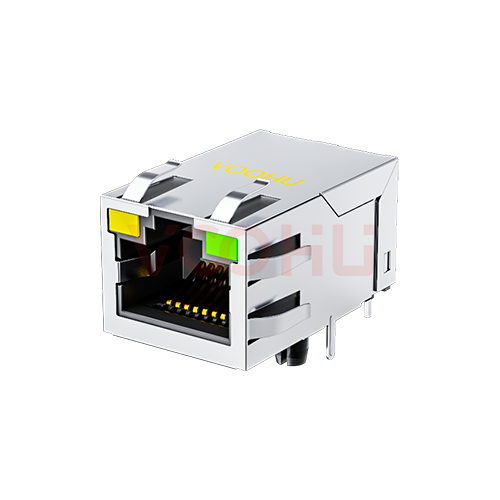
Würth Elektronik 7499010121A Alternative: VOOHU SYT311B083DB1A4DN Comparison
What is an alternative to the Würth 7499010121A? VOOHU SYT311B083DB1A4DN is a functional alternative — verify with samples in your design. Both are single-port, tab-up MagJacks (RJ45 jacks with integrated magnetics) for 10/100 Ethernet, through-hole, rated −40 to +85 °C, with 350 µH minimum OCL, the same PHY-side pin numbers and yellow-left / green-right LEDs on pins 9 to 12. The two drawings print the same centre distances for the locating posts (11.43 mm) and the shield pins (16.0 mm); the hole diameters are what differ — locating posts Ø3.25 mm against Ø3.20 mm, shield pins Ø1.60 mm against Ø1.63 mm (Würth / VOOHU).
产品SYT311B083DB1A4DN
7499010121A and SYT311B083DB1A4DN side by side
The left column comes from the Würth Elektronik 7499010121A datasheet (WE-RJ45LAN, revision 003.001, 2024-07-26); the right column comes from the VOOHU SYT311B083DB1A4DN datasheet, revision A0. Each cell names its page. Dimensions are in millimetres as printed, outline figures are width × depth × height, and "not stated" means the datasheet gives no value for that row.
| Item | Würth 7499010121A (source) | VOOHU SYT311B083DB1A4DN (source) |
|---|---|---|
| Speed | 100BASE-TX; compliant with IEEE 802.3u (DS p3) | 10/100BASE (DS p1, p3 title) |
| Ports / tab | 1 × 1, tab up (DS p1 title block) | 1 × 1, tab up (DS p1 title) |
| Mounting | Through-hole (DS p1 recommended hole layout) | Through-hole (DS p1 recommended PCB layout) |
| Outline W × D × H | 16.1 × 25.4 × 13.55; untoleranced ±0.25 (DS p1) | 16.20 × 25.30 × 13.45 (DS p1) |
| Pin length below board | 3.2 (DS p1) | 3.40 ±0.3 (DS p1) |
| Signal holes | 8 × Ø0.90 (DS p1) | 8 × Ø0.89 (DS p1) |
| Signal pitch / row spacing | 1.27 / not stated (DS p1) | 1.27 / 2.54 (DS p1) |
| Locating-post holes | 2 × Ø3.25, 11.43 apart (DS p1) | 2 × Ø3.20, 11.43 apart (DS p1) |
| Shield-pin holes | 2 × Ø1.60, 16.0 apart (DS p1) | 2 × Ø1.63, 16.00 apart (DS p1) |
| LED holes | 4 × Ø1.02; 13.72, 10.93 and 5.85 dimensioned (DS p1) | 4 × Ø1.02; 10.93 and 5.85 dimensioned (DS p1) |
| PHY-side pins | TD+ 1, CTD 2, TD− 3, RD+ 4, CRD 5, RD− 6 (DS p2) | TD+ 1, CT 2, TD− 3, RD+ 4, CT 5, RD− 6 (DS p3) |
| Cable-side termination | Two centre taps and two unused pairs, each through 75 Ω, to 0.001 µF / 2 kV, then pin 8 (DS p2) | Two centre taps and two unused pairs, each through 75 Ω, to 1000 pF / 2 kV, then GND pin 8 (DS p3) |
| Magnetics per channel | Transformer, then common-mode choke (DS p2) | 1CT:1 transformer, then line-side common-mode choke (DS p3) |
| LEDs | Yellow left, pins 12 (+) / 11; green right, pins 10 (+) / 9 (DS p2, p3) | Yellow left, 12 → 11; green right, 10 → 9 (DS p3) |
| LED forward voltage at 20 mA | 1.8–2.4 V (DS p3) | Green 1.85–2.45 V; yellow 1.7–2.2 V (DS p3) |
| OCL | 350 µH min, 100 kHz, 100 mV, 8 mA (DS p3) | 350 µH min, 100 kHz, 100 mV, 8 mA DC (DS p3) |
| Turns ratio | 1:1 ±2% (DS p3) | 1CT:1CT ±2% (DS p3) |
| Insertion loss, 1–100 MHz | −1 dB max (DS p3) | −1.0 dB max (DS p3) |
| Return loss, min | −18 dB (1–30 MHz), −12 dB (30–60 MHz), −10 dB (60–80 MHz), −8 dB (80–100 MHz) (DS p3) | −20 dB (1–10 MHz), −16 dB (10–30 MHz), −12 dB (30–60 MHz), −10 dB (60–80 MHz) (DS p3) |
| Crosstalk, min | −32 dB (1–60 MHz), −30 dB (60–100 MHz) (DS p3) | −40 dB (1–30 MHz), −35 dB (30–60 MHz), −30 dB (60–100 MHz) (DS p3) |
| Common-mode rejection, min | −35 dB (1–30 MHz), −32 dB (30–60 MHz), −30 dB (60–100 MHz) (DS p3) | −30 dB (1–100 MHz) (DS p3) |
| Isolation test | 2250 V DC min, 1 min (DS p3) | 1500 V AC and 2250 V DC, 6 s, 1 mA, primary to secondary (DS p3) |
| Operating temperature | −40 to +85 °C (DS p3) | −40 to +85 °C (DS p1) |
| Mating cycles | 750 min (DS p3) | 750 min (DS p1) |
What to check before a 7499010121A board takes SYT311B083DB1A4DN
Locating posts and shield pins. The centre distances agree on paper: 11.43 mm between the two locating posts and 16.0 mm between the two shield pins on both drawings. The holes themselves are sized a little differently. Würth calls for Ø3.25 mm locating-post holes and Ø1.60 mm shield-pin holes; VOOHU calls for Ø3.20 mm and Ø1.63 mm. If your fabrication drawing already carries the Würth sizes, build a few sample boards with SYT311B083DB1A4DN and check how the posts and shield pins seat and solder before you release the change.
Signal rows. Both parts use eight signal pins on a 1.27 mm pitch, with holes of Ø0.90 mm (Würth) and Ø0.89 mm (VOOHU). The Würth drawing does not print a number for the spacing between its two staggered rows; the VOOHU drawing gives 2.54 mm. Take the row spacing from the VOOHU drawing when you lay the two patterns over each other, rather than assuming a value for the Würth part.
Front opening and board thickness. The outlines are within about a tenth of a millimetre of each other: 16.1 × 25.4 × 13.55 mm for Würth and 16.20 × 25.30 × 13.45 mm for VOOHU (width × depth × height). The VOOHU jack is 0.1 mm wider and 0.1 mm lower, so check it in the enclosure cut-out and against any light pipe or panel gasket. The pins reach 3.2 mm below the board on the Würth drawing and 3.40 ±0.3 mm on the VOOHU drawing; on a thick board, confirm the protrusion your soldering process needs.
Schematic. The PHY-side pin numbers are the same on both datasheets — TD+ 1, centre tap 2, TD− 3, RD+ 4, centre tap 5, RD− 6 — so the PHY nets and centre-tap decoupling carry over. On the cable side, both datasheets draw the same termination network: the two centre taps and the two unused pairs each go through 75 Ω to a 1000 pF (0.001 µF), 2 kV capacitor that returns to pin 8. VOOHU labels pin 8 GND. Tie it to chassis or shield ground as your existing design does.
Isolation test conditions. Würth specifies 2250 V DC minimum for 1 minute. VOOHU specifies two conditions, 1500 V AC and 2250 V DC, each for 6 seconds at 1 mA from primary to secondary. The 2250 V DC figure appears on both datasheets, but a 1-minute hold and a 6-second hold are separate test methods, so this page quotes each as printed. If your safety file or customer drawing names the 1-minute condition, send it with your sample request and our FAE team will review it against the VOOHU test condition.
LEDs. The LED connection carries over: yellow at the left on pins 12 (anode) and 11, green at the right on pins 10 (anode) and 9, on both datasheets. Würth gives one forward-voltage range, 1.8–2.4 V at 20 mA; VOOHU gives it per colour, 1.85–2.45 V for green and 1.7–2.2 V for yellow at 20 mA. Recheck the series resistors with the VOOHU figures if your LED current is set close to a limit.
How do the transmission specifications line up?
Four lines carry the same values on both datasheets: OCL of 350 µH minimum at 100 kHz, 100 mV with 8 mA DC bias; turns-ratio tolerance of ±2%; insertion loss of −1 dB maximum from 1 to 100 MHz; and −30 dB common-mode rejection in the 60–100 MHz band. Return loss, crosstalk and the lower common-mode bands are written over different frequency splits, as the table shows. Because the bands do not coincide, compare each line with the magnetics requirements in your PHY vendor's design guide instead of reading one column against the other.
Where a 10/100 tab-up RJ45 MagJack rated −40 to +85 °C fits
SYT311B083DB1A4DN suits equipment with one 100 Mb/s copper port that has to work across −40 to +85 °C: industrial controllers and I/O modules, building-automation and metering nodes, serial-to-Ethernet gateways and outdoor control boxes. With the tab up, the latch faces away from the board. For a gigabit port, start from the RJ45 selector instead.
FAQ
Q1: What is an alternative to Würth 7499010121A?
VOOHU SYT311B083DB1A4DN is a functional alternative to the Würth Elektronik 7499010121A — verify with samples in your design. Both are 1 × 1, tab-up 10/100 RJ45 jacks with integrated magnetics, through-hole and rated −40 to +85 °C, with matching PHY-side pin numbers, 75 Ω termination to a 2 kV capacitor on pin 8 and yellow-left / green-right LEDs. Locating-post holes are Ø3.25 mm (Würth) and Ø3.20 mm (VOOHU); shield-pin holes are Ø1.60 mm and Ø1.63 mm.
Q2: Is the 7499010121A tab up or tab down, and is SYT311B083DB1A4DN the same?
Both are tab up. The Würth title block reads "1x1, up" and the VOOHU datasheet title reads "TAB-UP 1X1". Both datasheets place the yellow LED on the left and the green LED on the right.
Q3: What is the MagJack pinout of the 7499010121A and SYT311B083DB1A4DN?
Pins 1 to 6 are the PHY side on both datasheets: TD+ 1, transmit centre tap 2, TD− 3, RD+ 4, receive centre tap 5 and RD− 6. Pin 8 is the return of the cable-side 75 Ω / 2 kV termination (labelled GND by VOOHU). The LEDs use pins 9 to 12: green between 10 (anode) and 9, yellow between 12 (anode) and 11.
Q4: What does the RJ45 with magnetics schematic look like in these two jacks?
Each channel has a transformer on the PHY side followed by a common-mode choke toward the cable. The transmit and receive windings have centre taps brought out to pins 2 and 5. On the cable side, the centre taps and the two unused pairs are each terminated through 75 Ω into a 1000 pF, 2 kV capacitor tied to pin 8. Würth and VOOHU draw the same arrangement; Würth writes the turns ratio as 1:1 and VOOHU as 1CT:1CT, both ±2%.
Check SYT311B083DB1A4DN on your 7499010121A layout
Send the hole drawing of your current 7499010121A footprint and the front-panel cut-out dimensions with the sample request form. Samples are available for evaluation, and selected parts are free of charge. Our FAE team will be glad to confirm the options for your project. Our FAE team can suggest suitable parts and help check the design — for SYT311B083DB1A4DN, the locating-post and shield-pin hole sizes against your board, the fit in your enclosure opening and the isolation test condition your product needs. VOOHU supplies RJ45 and SFP connectors, LAN and PoE transformers and common mode chokes from Suzhou, China, to more than 1,500 customers.
Other tab-up jacks with integrated magnetics are listed in the RJ45 connector selector, which opens with both filters set.
Related product: SYT311B083DB1A4DN — 1 × 1 tab-up 10/100 RJ45 jack with integrated magnetics, yellow / green LEDs, 75 Ω / 2 kV cable-side termination, −40 to +85 °C, through-hole. Other Würth jacks we have compared: 7499111001A and 7499111121A.
方案/solution-ethernet/