




Initial inductance
Measured at low current before any roll-off. Ranges from about 100 to 500 nanohenries across the WHPBU series, which suits high frequency multiphase stages.
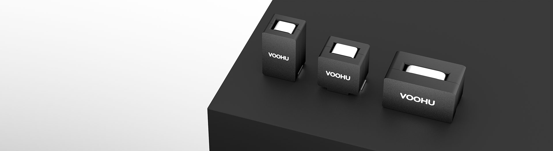
Produits d’inductance
These are single-winding power bead inductors for multiphase buck converters and point-of-load stages: nanohenry inductance, sub-milliohm DC resistance and saturation currents past a hundred amps. Select on the hot saturation figure and the heating current, not the room-temperature number.
Recherche et sélection de références
Le tableau utilise les fiches produits actuelles du site anglophone, les critères de sélection publiés et les liens vers les fichiers techniques propres à chaque référence.
* Colonnes Image et Référence figées · faites glisser horizontalement pour consulter toutes les caractéristiques
| Image | Fiche technique | Comparer | Téléchargements |
Catégorie
|
Inductance initiale (nH)
|
Tolérance (± %)
|
DCR(mΩ)
|
1 – Courant de saturation à 25 °C (A), typ.
|
2 – Courant de saturation à 100 °C (A), typ.
|
Courant d’échauffement (A), typ.
|
Échantillon |
|---|
| Image | Référence | Fiche technique | Comparer | Téléchargements | Catégorie | Inductance initiale (nH) | Tolérance (± %) | DCR(mΩ) | 1 – Courant de saturation à 25 °C (A), typ. | 2 – Courant de saturation à 100 °C (A), typ. | Courant d’échauffement (A), typ. | Échantillon |
|---|---|---|---|---|---|---|---|---|---|---|---|---|
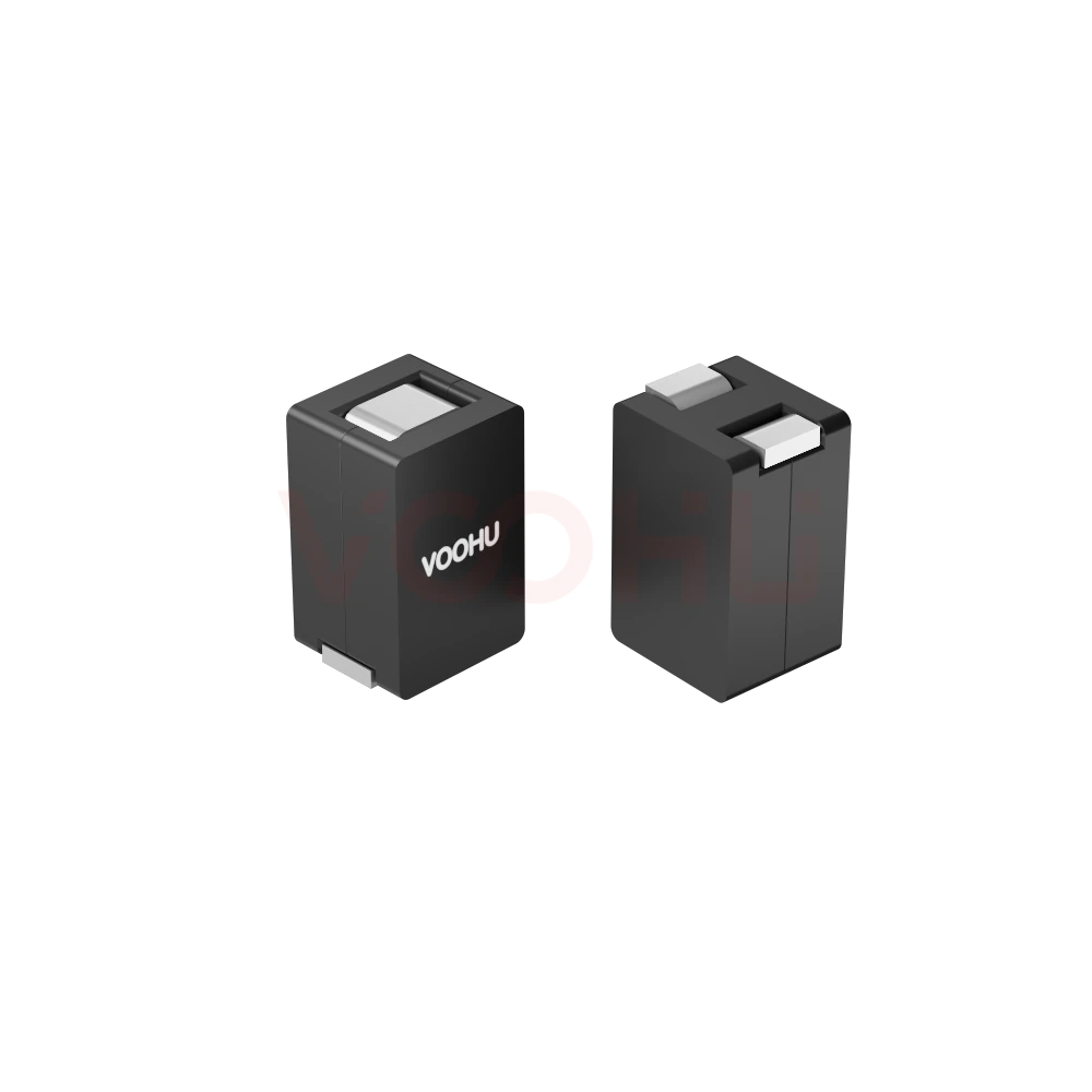 |
WHPBU-131308N-R50L0 | SPEC | WHPBU-131308N | 500 | 15 | 0.32 ± 9.4% | 28 | 23 | 45 |
|
||
|
|
WHPBU-131308N-R44L0 | SPEC | WHPBU-131308N | 440 | 15 | 0.32 ± 9.4% | 35 | 25 | 45 |
|
||
|
|
WHPBU-131308N-R32L0 | SPEC | WHPBU-131308N | 320 | 15 | 0.32 ± 9.4% | 50 | 35 | 45 |
|
||
|
|
WHPBU-131308N-R26L0 | SPEC | WHPBU-131308N | 260 | 15 | 0.32 ± 9.4% | 60 | 45 | 45 |
|
||
|
|
WHPBU-131308N-R21L0 | SPEC | WHPBU-131308N | 210 | 15 | 0.32 ± 9.4% | 70 | 55 | 45 |
|
||
|
|
WHPBU-131308N-R11K0 | SPEC | WHPBU-131308N | 110 | 10 | 0.32 ± 9.4% | 120 | 105 | 45 |
|
Élargissez les filtres sélectionnés ou effacez la recherche en cours.
By series
Series differ in body size, which sets DC resistance and how much current each phase carries.
Comment sélectionner
Phase count and ripple set the inductance; thermals and peak current set the series.
Work from input and output voltage, switching frequency, phase count and the ripple you can accept. More phases and higher frequency both reduce the inductance each phase needs.
Use the saturation figure at 100 degrees, not the 25 degree number. Your per-phase peak, including load transients, has to stay inside it.
Heating current caps the continuous RMS per phase. Multiply DC resistance by that current squared to see the copper loss the board has to shed.
Check body size, land pattern and phase-to-phase spacing, then measure ripple, current sharing and temperature rise on the real board.
Parameters
Two saturation figures and a heating current, each defined under different conditions.
Measured at low current before any roll-off. Ranges from about 100 to 500 nanohenries across the WHPBU series, which suits high frequency multiphase stages.
Stated as a percentage around the initial inductance. It feeds directly into your ripple calculation, so use the worst-case corner rather than the nominal value.
Sub-milliohm across the range, from about 0.18 to 0.47 milliohm depending on series. At high phase current even a tenth of a milliohm is measurable heat.
The room-temperature limit, useful for comparing parts but optimistic for design. A real converter runs hotter than its test bench.
The figure to design against. Saturation capability falls as the core heats, so this is what your peak phase current must stay below.
The continuous RMS current that produces the datasheet's stated temperature rise. It caps steady-state load, while saturation caps the peak.
Comparer
DC resistance and heating current separate the series more than inductance does.
Revenir au sélecteur ↑| Catégorie | Références | Inductance initiale (nH) | Tolérance (± %) | DCR(mΩ) | 1 – Courant de saturation à 25 °C (A), typ. | 2 – Courant de saturation à 100 °C (A), typ. | Courant d’échauffement (A), typ. | Action |
|---|---|---|---|---|---|---|---|---|
| WHPBU-100705N | 7 | 72, 100, 120, 150, 200, 220, 300 | 15 | 0.325±7% | 19, 30, 33, 45, 65, 70, 80 | 12, 24, 25, 35, 50, 60, 70 | 31 | Filtrer → |
| WHPBU-100710N | 8 | 100, 120, 150, 180, 220, 300, 330, 470 | 15, 20 | 0.18±10% | 20, 35, 43, 60, 75, 90, 117 | 15, 30, 33, 50, 65, 75, 80, 100 | 70 | Filtrer → |
| WHPBU-131308N | 6 | 110, 210, 260, 320, 440, 500 | 10, 15 | 0.32 ± 9.4% | 28, 35, 50, 60, 70, 120 | 23, 25, 35, 45, 55, 105 | 45 | Filtrer → |
| WHPBU-150705N | 3 | 100, 120, 150 | 15 | 0.47±7% | 72, 87, 105 | 60, 75, 80 | 53 | Filtrer → |
Analyse de l’application
Confirm phase count, per-phase current, switching frequency and the thermal environment.
Documents
Datasheets carry the saturation curves, heating current and recommended land pattern.
Affichage de jeux de fichiers disponibles représentatifs. Recherchez un SKU précis.
Le contenu produit publié par VOOHU est vérifié par son équipe technique. Les caractéristiques, les téléchargements et les informations d’assistance technique sont associés à des références précises afin que vous puissiez les vérifier avant de demander des échantillons ou un devis.
Présentation de la catégorie
These parts are often mislabelled. Knowing what they are, and which of the three current figures to design against, prevents most of the errors.
Discuter d’une nouvelle conception
Contacter l’équipe FAE pour une évaluation de remplacement.
Vous avez déjà une référence ? Demander des échantillons ou un devis.
A power bead inductor is a single winding of one or two turns over a ferrite core. It is not a coupled inductor and not a common mode choke, both of which have two windings that interact magnetically. The construction gives very low DC resistance and very high saturation current in a small body.
Saturation at 25 degrees is a comparison number. Saturation at 100 degrees is the one your peak phase current must stay under, because the core loses capability as it heats. Heating current is the continuous RMS that produces the rated temperature rise. Size the peak on the hot figure, the steady state on heating current.
With phase currents in the tens of amps, loss rises with the square of current. A part at 0.18 milliohm and one at 0.47 milliohm differ by more than a factor of two in copper loss. On a dense multiphase board that shows up directly as board temperature, so read DCR early rather than last.
FAQ
Answers cover what a power bead is, which current rating to design against and how to compare.
It is a single-winding power inductor, usually one or two turns over a ferrite core, designed for very low DC resistance and very high saturation current in a small body. It is the standard choice for multiphase buck converters powering processors, FPGAs and ASICs, where each phase carries tens of amps at low inductance.
No. A coupled inductor has two or more windings that interact magnetically and is used to shape ripple across phases. A power bead is a single winding with no magnetic coupling between phases. The two are not interchangeable, and the datasheets describe different things, so do not substitute one for the other.
The figure at 100 degrees. Saturation capability falls as the core heats, and a working converter runs well above room temperature. The 25 degree number is useful for comparing parts on equal terms, but sizing a design against it leaves no margin once the board is hot.
Heating current is the continuous RMS current that produces the temperature rise stated in the datasheet. It caps the steady-state load each phase can carry. Saturation current caps the instantaneous peak. Both have to be satisfied: heating current for the average, hot saturation for the transient.
Because loss rises with the square of current, and phase currents here are tens of amps. Across the WHPBU range DC resistance runs from about 0.18 to 0.47 milliohm, which is more than a factor of two in copper loss at the same current. On a dense board that shows up directly as temperature.
Work from input and output voltage, switching frequency, phase count and the ripple current you can accept. More phases and higher switching frequency both reduce the inductance each phase needs, which is why these parts are specified in nanohenries rather than microhenries.
It is not advisable. Phases should be as identical as possible, because differences in inductance and DC resistance cause unequal current sharing, and the phase carrying the most current runs hottest and saturates first. Use the same part across all phases and verify the sharing by measurement.
With a complete part number, send the part number, quantity, delivery region and the date you need it. If you are still selecting, send the total output current, phase count, per-phase RMS and peak current, switching frequency and ambient temperature.
Assistance technique
Envoyez la référence candidate et la condition à examiner. Vous pourrez demander des échantillons une fois la sélection précisée ; les questions commerciales peuvent être abordées au cours du même échange technique.
Indiquez la révision du document
Température, tension d’isolement et conditions de courant PoE prises comme référence
Nombre de broches, pas et espacement entre les rangées de broches
Pour faciliter la priorisation des échantillons et de l’évaluation
Date à laquelle vous avez besoin de références candidates et d’un comparatif des différences
L’analyse technique identifie les références candidates et explique les différences.
Issues du sélecteur ou de l’analyse technique
Prototypage / présérie / production
Précisez séparément les délais des échantillons et de la production
Documents de conformité, déclarations de matières ou rapports de tiers
La quantité d’échantillons, le délai et le coût dépendent de la phase du projet et de la référence. L’équipe commerciale répond les jours ouvrés.




