




Package size and dimensions
Stated as length by width by height in millimetres. Height is often the binding constraint, and within one footprint the taller option usually carries more current.
Produits d’inductance
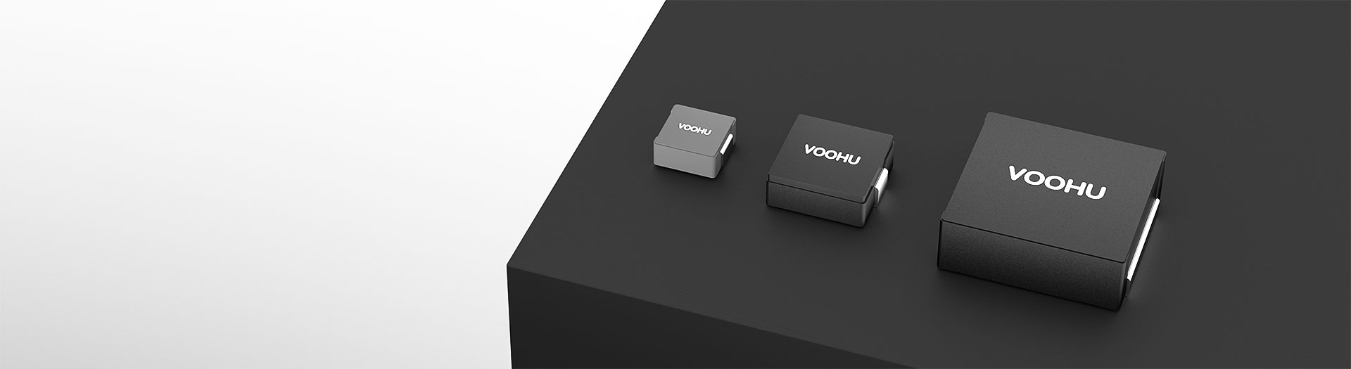
Molded construction encloses the winding in a magnetic compound, giving a self-shielded part with low audible noise and a soft saturation curve. The range runs from 4.4 by 4.2 millimetres up to 23.5 by 22, covering 0.1 to 150 microhenries and RMS currents to 70 amps.
Recherche et sélection de références
Le tableau utilise les fiches produits actuelles du site anglophone, les critères de sélection publiés et les liens vers les fichiers techniques propres à chaque référence.
* Colonnes Image et Référence figées · faites glisser horizontalement pour consulter toutes les caractéristiques
| Image | Fiche technique | Comparer | Téléchargements |
Dimensions du boîtier
|
Dimensions (L×l×H)
|
Valeur d’inductance
|
DCR(mΩ)
|
IRMS
|
ISAT
|
Échantillon |
|---|
| Image | Référence | Fiche technique | Comparer | Téléchargements | Dimensions du boîtier | Dimensions (L×l×H) | Valeur d’inductance | DCR(mΩ) | IRMS | ISAT | Échantillon |
|---|---|---|---|---|---|---|---|---|---|---|---|
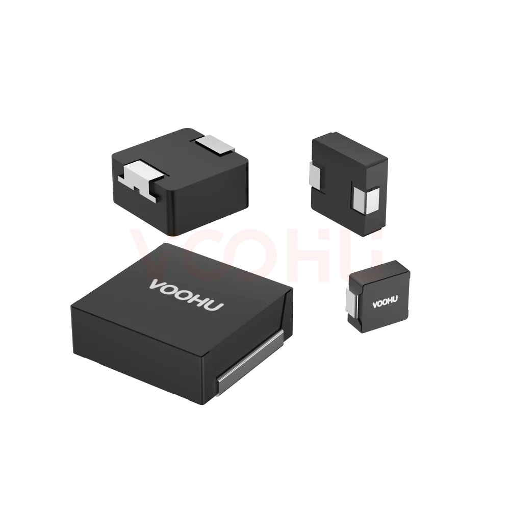 |
WHYT2313 series | SPEC | Série WHYT | 23.5*22*12.6mm | 1.00-100.00uH | 0.95-40mΩ | 11-70A | 9-60A |
|
||
|
|
WHYT1770 series | SPEC | Série WHYT | 17.15*17.15*7mm | 2.2-100uH | 2.5-130mΩ | 3.7-29A | 5-34A |
|
||
|
|
WHYT1265 series | SPEC | Série WHYT | 13.45*12.6*6.5mm | 4.7-100uH | 8.5-170mΩ | 3.5-16A | 4-24A |
|
||
|
|
WHYT1260 series | SPEC | Série WHYT | 13.45*12.6*5.8mm | 4.7-150uH | 9-350mΩ | 1.5-15A | 2.7-24A |
|
||
|
|
WHYT1250 series | SPEC | Série WHYT | 13.45*12.6*4.8mm | 0.22-47uH | 0.7-130mΩ | 3-50A | 5-75A |
|
||
|
|
WHYT1050 series | SPEC | Série WHYT | 11.5*10*4.8mm | 0.22-100uH | 0.8-290mΩ | 2.1-37A | 2.8-65A |
|
||
|
|
WHYT1040 series | SPEC | Série WHYT | 11.5*10*3.8mm | 0.15-100uH | 0.65-340mΩ | 2-45A | 2.3-75A |
|
||
|
|
WHYT1030 series | SPEC | Série WHYT | 11.5*10*2.8mm | 0.22-33uH | 0.89-160mΩ | 4-50A | 2.6-33A |
|
||
|
|
WHYT0650 series | SPEC | Série WHYT | 7.0*6.6*4.8mm | 0.47-47uH | 3.9-230mΩ | 2-20A | 2.6-21A |
|
||
|
|
WHYT0640 series | SPEC | Série WHYT | 7.0*6.6*3.8mm | 0.68-47uH | 4.8-320mΩ | 1.8-17A | 2.5-19A |
|
||
|
|
WHYT0630 series | SPEC | Série WHYT | 7.0*6.6*2.8mm | 0.22-47uH | 3-385mΩ | 1.5-24A | 2-34A |
|
Élargissez les filtres sélectionnés ou effacez la recherche en cours.
By series
Series split by footprint and height, which together set current capability and loss.
Comment sélectionner
Ripple sets the inductance; IRMS and ISAT set the size; height often decides.
Derive it from input and output voltage, switching frequency and the ripple current you can accept. Then check the tolerance band at its worst corner.
IRMS caps the continuous current by temperature rise. ISAT caps the peak by inductance roll-off. Your design has to satisfy both, not the friendlier one.
Larger footprints and taller bodies give lower DC resistance and higher current. Work back from the height clearance over the converter.
Measure ripple, efficiency and the inductor's temperature at full load in the real enclosure, then confirm at the highest rated ambient.
Parameters
IRMS and ISAT are defined differently and both have to be satisfied.
Stated as length by width by height in millimetres. Height is often the binding constraint, and within one footprint the taller option usually carries more current.
Ranges from about 0.1 to 150 microhenries across the family. Low values suit high switching frequency; higher values reduce ripple at lower frequency.
From about 0.65 milliohm on the largest low-value parts up to several hundred milliohms on the small high-inductance ones. It sets conduction loss.
The continuous RMS current producing the datasheet's stated temperature rise. It is the steady-state limit and must be derated for high ambient temperature.
The current at which inductance falls by the stated percentage. It caps the instantaneous peak, including startup inrush and load transients.
Molded construction encloses the winding in magnetic material, so the part is inherently shielded. That reduces coupling into nearby traces and lowers audible noise.
Comparer
Footprint and height together decide what current and inductance are available.
Revenir au sélecteur ↑| Dimensions du boîtier | Références | Dimensions (L×l×H) | Valeur d’inductance | DCR(mΩ) | IRMS | ISAT | Action |
|---|---|---|---|---|---|---|---|
| Série WHYT | 11 | 7.0*6.6*2.8mm, 7.0*6.6*3.8mm, 7.0*6.6*4.8mm, 11.5*10*2.8mm, 11.5*10*3.8mm, 11.5*10*4.8mm, 13.45*12.6*4.8mm, 13.45*12.6*5.8mm, 13.45*12.6*6.5mm, 17.15*17.15*7mm, 23.5*22*12.6mm | 0.22-47uH, 0.68-47uH, 0.47-47uH, 0.22-33uH, 0.15-100uH, 0.22-100uH, 4.7-150uH, 4.7-100uH, 2.2-100uH, 1.00-100.00uH | 3-385mΩ, 4.8-320mΩ, 3.9-230mΩ, 0.89-160mΩ, 0.65-340mΩ, 0.8-290mΩ, 0.7-130mΩ, 9-350mΩ, 8.5-170mΩ, 2.5-130mΩ, 0.95-40mΩ | 1.5-24A, 1.8-17A, 2-20A, 4-50A, 2-45A, 2.1-37A, 3-50A, 1.5-15A, 3.5-16A, 3.7-29A, 11-70A | 2-34A, 2.5-19A, 2.6-21A, 2.6-33A, 2.3-75A, 2.8-65A, 5-75A, 2.7-24A, 4-24A, 5-34A, 9-60A | Filtrer → |
| Série WHYTA | 7 | 4.4*4.2*1.0mm, 4.4*4.2*1.8mm, 5.4*5.2*1.6mm, 5.4*5.2*2.8mm, 7.0*6.6*1.3mm, 7.0*6.6*1.6mm, 7.0*6.6*2.2mm | 0.15-4.7uH, 0.1-10uH, 0.47-10uH, 0.1-22uH, 0.22-22uH | 9-195mΩ, 4-282mΩ, 9-155mΩ, 3-125mΩ, 8.5-175mΩ, 2.3-350mΩ, 3-230mΩ | 1.8-7.5A, 1.6-13A, 2.5-10.5A, 3.2-25A, 2-10A, 1.8-25A, 2-21A | 2.2-15A, 2-22A, 3-15.5A, 3.5-30A, 3-16A, 2.3-38A, 2.5-34A | Filtrer → |
| Série WHYTP | 1 | 3.4*3.2*1.8mm | 0.33-10uH | 21-422mΩ | 1.4-8A | 1.6-10A | Filtrer → |
Analyse de l’application
Confirm output current, switching frequency, ripple budget and height clearance.
Documents
Datasheets carry the saturation curve, temperature rise data and land pattern.
Affichage de jeux de fichiers disponibles représentatifs. Recherchez un SKU précis.
Le contenu produit publié par VOOHU est vérifié par son équipe technique. Les caractéristiques, les téléchargements et les informations d’assistance technique sont associés à des références précises afin que vous puissiez les vérifier avant de demander des échantillons ou un devis.
Présentation de la catégorie
Two questions decide most molded inductor selections: whether the construction is right for the design, and which of the two current figures limits you.
Discuter d’une nouvelle conception
Contacter l’équipe FAE pour une évaluation de remplacement.
Vous avez déjà une référence ? Demander des échantillons ou un devis.
The winding is encased in a magnetic composite rather than wound on an exposed core. That makes the part self-shielding, so it couples less into neighbouring traces, and it damps the movement that causes audible buzz. It also gives a softer saturation curve, where inductance falls gradually rather than collapsing.
IRMS is a thermal limit: the continuous RMS current that produces the stated temperature rise. ISAT is a magnetic limit: the current at which inductance has dropped by a stated percentage. A design has to satisfy both. Steady-state load is checked against IRMS, and peaks including startup inrush against ISAT.
Within the same footprint, a taller body has more winding volume, which means lower DC resistance and higher current for the same inductance. The range spans from one millimetre high up to more than twelve. In practice the clearance over the converter often decides the series before any electrical parameter does.
FAQ
Answers cover molded versus wirewound, IRMS against ISAT, and shielding.
It is an inductor whose winding is encased in a magnetic composite material rather than wound on an exposed core. The construction makes the part self-shielding, reduces audible noise and gives a softer saturation characteristic. They are widely used in DC-DC converters where board space and magnetic coupling both matter.
Molded parts are self-shielded, so they couple less noise into nearby traces, and they are quieter because the winding cannot move. Their saturation curve is softer, falling gradually rather than collapsing. Open wirewound parts can offer lower cost at some sizes. Compare on DCR, IRMS, ISAT and the shielding your layout needs.
IRMS is a thermal rating: the continuous RMS current that produces the temperature rise stated in the datasheet. ISAT is a magnetic rating: the current at which inductance has fallen by a stated percentage. Both must be satisfied, IRMS for steady-state load and ISAT for peaks including startup inrush.
It depends on the load profile. A steady high current load is usually limited by IRMS and temperature rise. A load with large fast transients, or a converter with significant startup inrush, is usually limited by ISAT. Check both against your actual current waveform rather than assuming.
Start from the height clearance over the converter, because that is often the binding mechanical constraint. Within a footprint, a taller body gives lower DC resistance and higher current for the same inductance. Then confirm the band you can fit still meets both current ratings with margin.
It reduces two things. Magnetically, the enclosed winding radiates less into neighbouring traces, which helps in dense layouts. Acoustically, the encapsulation damps the winding movement that causes audible buzz at switching frequencies in the audio band. Verify both on your own assembly.
IRMS is defined for a stated temperature rise from a stated ambient. If your enclosure runs hotter or has restricted airflow, the usable current is lower. Measure the part's temperature at full load in the real enclosure at the highest rated ambient rather than trusting the headline figure.
With a complete part number, send the part number, quantity, delivery region and the date you need it. If you are still selecting, send the output current, switching frequency, ripple budget, height clearance and ambient temperature, and a sales engineer will shortlist candidates.
Assistance technique
Envoyez la référence candidate et la condition à examiner. Vous pourrez demander des échantillons une fois la sélection précisée ; les questions commerciales peuvent être abordées au cours du même échange technique.
Indiquez la révision du document
Température, tension d’isolement et conditions de courant PoE prises comme référence
Nombre de broches, pas et espacement entre les rangées de broches
Pour faciliter la priorisation des échantillons et de l’évaluation
Date à laquelle vous avez besoin de références candidates et d’un comparatif des différences
L’analyse technique identifie les références candidates et explique les différences.
Issues du sélecteur ou de l’analyse technique
Prototypage / présérie / production
Précisez séparément les délais des échantillons et de la production
Documents de conformité, déclarations de matières ou rapports de tiers
La quantité d’échantillons, le délai et le coût dépendent de la phase du projet et de la référence. L’équipe commerciale répond les jours ouvrés.




