Creepage vs Clearance in Transformer Isolation Design
Clearance is the shortest distance through air between two conductive parts. Creepage distance is the shortest path between the same two parts along the surface of the insulation. Clearance prevents a flashover through the air when a transient overvoltage arrives, so it is set mainly by peak and transient voltages and by altitude. Creepage prevents tracking, a conductive path that forms slowly along a contaminated surface, so it is set by the RMS working voltage, the pollution degree and the insulating material. Creepage and clearance matter because either one, if too short, can break the isolation barrier that protects people and low-voltage circuits. In a transformer, both have to hold between primary and secondary inside the part, across its body and on the PCB under it. Several VOOHU isolation transformer datasheets state these values directly, from 7 mm to 15 mm.
What is the difference between clearance and creepage?
Clearance and creepage are measured between the same two conductors, but along different paths. On a flat, bare surface they are the same length. Add a slot, a groove or a low rib in the insulation and the surface path gets longer while the air path does not.
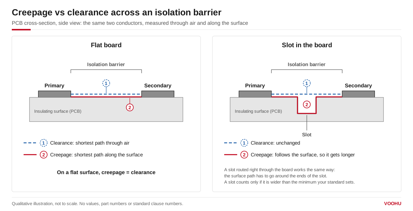
Clearance is the straight line through air between primary and secondary; creepage follows the surface. A slot in the board lengthens the creepage path but leaves the clearance unchanged. Illustration only, not to scale.
| Clearance | Creepage distance | |
|---|---|---|
| Measured | Shortest straight path through air | Shortest path along the surface of the insulation |
| Failure it prevents | Air breakdown and flashover during a transient overvoltage | Tracking: a leakage path that builds up over time on a polluted surface |
| Set mainly by | Peak working voltage and expected transient overvoltages; altitude | RMS working voltage; pollution degree; material group of the insulation |
| Changes with altitude | Yes, thinner air breaks down more easily | Not directly |
| How to increase it | Move the conductors apart, or add a barrier that blocks the straight path | Slots, ribs or grooves in the insulation; wider pin spacing; keeping copper back from the barrier |
Why is creepage and clearance important?
An isolation barrier is only as strong as its shortest path. Clearance that is too short can flash over during a surge; creepage that is too short can pass a test when new and then track after months in a dusty or humid enclosure. Safety evaluations of isolated products check both distances, alongside the solid insulation. A hi-pot test is a separate check: it applies a high voltage for a set time and confirms the insulation does not break down, but it does not measure distances. Thehi-pot test for Ethernet portsis covered separately.
What is the IEC standard for creepage and clearance?
The basic standard isIEC 60664-1, insulation coordination for equipment within low-voltage supply systems. It covers equipment rated up to 1,000 V AC or 1,500 V DC, applies up to 2,000 m above sea level with guidance for higher altitudes, and gives the requirements from which technical committees set clearances, creepage distances and criteria for solid insulation. Product safety standards then set what your product needs. For audio, video, information and communication technology equipment that isIEC 62368-1; medical electrical equipment uses IEC 60601-1. Work from the standard your product will be evaluated to, in its current edition, and check that the transformer datasheet names the insulation grade and working voltage you need.
How to calculate creepage and clearance?
There is no formula; you look the values up in the tables of your product standard. The inputs are the same in every case:
- Insulation grade.Decide whether the two circuits need functional, basic, supplementary or reinforced insulation. Reinforced insulation, one insulation system that gives protection equivalent to double insulation, needs larger distances than basic insulation.
- Working voltage.Use the RMS working voltage for creepage and the peak working voltage for clearance. Creepage distance rises with voltage.
- Transient overvoltage.The overvoltage category of the supply sets the impulse the clearance must withstand.
- Pollution degree and material.The environment at the barrier and the tracking resistance of the insulating material, given as its material group, set the creepage.
- Altitude.Above 2,000 m, clearances need correcting.
That is why there is no single answer to a question such as "what is the minimum creepage distance for a 1000 V PCB": it depends on all five inputs. Online creepage and clearance calculators use the same tables, so check which standard and edition they follow.
What is creepage distance in a transformer?
In an isolation transformer, the barrier between primary and secondary has to hold in three places:
- Inside the part.Between the windings, isolation comes from the insulation system: wire insulation, tape, the bobbin and the margins that keep windings away from its edges. Here solid insulation matters as much as distance.
- Across the body.Between the primary pins and the secondary pins, along the package surface and through the air. A datasheet line such as "minimum creepage and clearance between primary and secondary" describes the part itself.
- On your PCB.Between the nearest primary and secondary copper: pads, traces, pours and vias under and around the part. The part's rating does not extend to your layout, so the board must meet the spacing your standard requires on its own. The same applies to any other part that straddles the barrier.
Datasheets state isolation in different ways, so read the insulation grade and working voltage, not only the kilovolt figure. Three VOOHU datasheets show the range:
| Part number | Insulation as stated | Creepage and clearance | Isolation test |
|---|---|---|---|
| WHST06001A0(WHST060xxA0 push-pull series) | Reinforced insulation (IEC 62368-1); 550 Vrms continuous | 8 mm minimum creepage and clearance, primary to secondary | 4 kVrms isolation |
| WHST06202E0(BMS isolation) | Reinforced insulation at a working voltage of 1500 VDC | Creepage 15 mm minimum; clearance 14 mm minimum | 8000 VDC, 1 mA, 60 s, or 5600 VAC, 1 mA, 60 s |
| WHSH16F01D4(LAN transformer) | Supplementary insulation at a working voltage of 250 Vrms; datasheet references IEC 60601-1 and IEC 60950-1 | Clearance 7 mm; creepage 10 mm | 4000 VAC, 1 mA, 60 s, or 4800 VAC, 1 mA, 1 s |
Do not derive a creepage distance or an insulation grade from a hi-pot voltage, or the other way round; they are separate ratings. Compare each with what your standard requires.
How to increase creepage distance
- Slot the board under the barrier.A routed slot between primary and secondary copper forces the surface path around the ends of the slot, so make it long enough to extend past the copper on both sides. Standards set a minimum slot width for it to count, so check yours.
- Keep copper back.Pull pours, traces and vias away from the barrier; the nearest pads usually set the distance. Do not route secondary-side traces under the primary half of the transformer, or the reverse.
- Choose the package for the spacing.A transformer with primary and secondary pins on opposite sides, and a datasheet that states the creepage you need, gives you a footprint that starts from a known distance.
- Use barriers for clearance.Grooves and low ribs lengthen creepage only; to gain clearance, a rib or barrier has to be tall enough to block the straight path through air.
Which VOOHU isolation transformer should you start from?
| Part | Fits when |
|---|---|
| WHST06001A0and the WHST060xxA0 series | An isolated push-pull supply needs reinforced insulation to IEC 62368-1, with 8 mm minimum creepage and clearance stated on the datasheet |
| WHST06202E0 | A BMS design with a high working voltage needs reinforced insulation at 1500 VDC, with 15 mm creepage and 14 mm clearance |
| WHSH16F01D4 | A LAN port needs a stated supplementary insulation rating at 250 Vrms, with 10 mm creepage and 7 mm clearance |
| WHS06709BA | A BMS isolation design tested at 4300 VDC, 1 mA, 60 s, or 3100 VAC, 1 mA, 2 s; our FAE team can confirm its creepage and clearance against your standard |
Compare more parts in thepush-pull transformer selectorand theBMS isolation transformer selector. For PoE power, see theEP13 series, and ask us to confirm the insulation data for your design.
产品WHST06001A0
产品WHSH16F01D4
FAQ
Q1: Can creepage be less than clearance?
No. Between the same two points, a path along a surface can never be shorter than the straight line through air, so the measured creepage is always equal to or longer than the clearance. The required values come from different tables, and the layout has to meet both. The WHSH16F01D4 datasheet shows the usual relationship: 7 mm clearance and 10 mm creepage.
Q2: Do creepage and clearance change with altitude?
Clearance does. Air at altitude breaks down at a lower voltage, and IEC 60664-1 applies up to 2,000 m with guidance for higher altitudes, so equipment used higher up needs larger clearances. Creepage is not normally corrected for altitude, but because creepage can never be shorter than clearance, a larger clearance can push the creepage up too.
Q3: What are creepage requirements for planar transformers?
In a planar transformer the windings are copper layers in a board or a stack, so the insulation between primary and secondary layers is solid insulation, judged on its thickness and material rather than on creepage. Creepage and clearance still apply where the layers reach the surface: at the board edges, around vias and pads, and between the terminations. Seeplanar transformer technologyfor how these parts are built.
Q4: What is reinforced insulation?
Reinforced insulation is a single insulation system that gives protection equivalent to double insulation, that is, basic plus supplementary insulation. It needs larger creepage and clearance than basic insulation at the same working voltage. A datasheet should state it together with the working voltage it applies to, as the WHST06202E0 datasheet does: reinforced insulation at a working voltage of 1500 VDC.
Ask us to check a transformer against your isolation requirement
Tell us the standard your product follows, the insulation grade and working voltage across the barrier, the pollution degree and altitude, and the board space you have, in thesample and support request form. Our FAE team can suggest a transformer whose datasheet insulation grade, creepage, clearance and isolation test match your requirement, and review the footprint spacing with you. Samples are available for evaluation, and selected parts are free of charge. Our FAE team will be glad to confirm the options for your project.
VOOHU supplies RJ45 and SFP connectors, LAN and PoE transformers and common mode chokes from Suzhou, China, to more than 1,500 customers.