USB ESD Protection: How to Choose ESD Diodes for USB 2.0 and Type-C Ports
USB ESD protection means placing an ESD diode on every line that leaves the board through the USB connector, as close to the connector as the layout allows, so that a discharge is diverted to ground before it reaches the USB controller. For the USB 2.0 data pair, D+ and D−, choose a part whose reverse working voltage (VRWM) is at least the 3.3 V signal level, whose capacitance is low enough for 480 Mbit/s signalling, whose clamping voltage stays below the absolute maximum rating of the chip behind it, and whose IEC 61000-4-2 rating covers your product test. VBUS and the Type-C CC pins need a working voltage of at least 5 V, and more when USB Power Delivery raises VBUS. VOOHU supplies low-capacitanceESD protection diodes, and our FAE team can help match them to your port.
Where is ESD protection required on a USB port?
Every pin a finger or plug can reach is an entry point, so each line at the connector needs protection: D+, D− and VBUS on a USB 2.0 Type-A, Type-B or Micro-B port. A USB Type-C receptacle adds two configuration channel pins, CC1 and CC2, which detect attachment, orientation and current advertisement, and two sideband pins, SBU1 and SBU2, used by audio accessory mode and alternate modes. The table summarises the per-line guidance in TI's application noteESD and Surge Protection for USB Interfaces(SLVAF82B).
| Line | What it carries | Working voltage (VRWM) | Capacitance |
|---|---|---|---|
| D+, D− | USB 2.0 data, up to 480 Mbit/s | 3.3 V or more | Below 4 pF (below 20 pF for 12 Mbit/s full-speed-only ports) |
| VBUS | Power: 5 V, or up to 48 V with USB Power Delivery | At or above the highest VBUS voltage the port can see | Not a signal line |
| CC1, CC2 (Type-C) | Attach, orientation and current detection | 5 V or more | No figure given |
| SBU1, SBU2 (Type-C) | Audio accessory and alternate modes | 3.6 V or more | Low, set by the alternate-mode signal rate |
Source: TI SLVAF82B, sections 2.2, 3.2, 7.2 and 8.1. USB 5 Gbps and faster TX/RX pairs need protection specified for their rate; this guide covers the USB 2.0 data path.
How does USB ESD protection work?
An ESD protection diode sits between the line and ground. Below its breakdown voltage it draws only leakage current, and the signal sees only its capacitance. When a discharge drives the line past breakdown, the diode conducts and steers the surge current to ground, holding the line near its clamping voltage. The chip behind it sees that voltage plus the drop across the inductance of the diode's connections, which is why the diode belongs at the connector, where the strike enters. Many data-line ESD arrays combine steering diodes with one Zener clamp, so one package protects several lines.
How to select an ESD protection diode for USB 2.0
- Working voltage.VRWM at or above the highest normal voltage on the line: 3.3 V for D+ and D−, 5 V for VBUS and CC on a 5 V port. Too low, and the part conducts during normal signalling.
- Capacitance.TI recommends less than 4 pF for USB 2.0 data lines. Check whether a datasheet gives capacitance line to ground or between lines, and at what bias and frequency, and use the same part on D+ and D− so both lines see the same load.
- Clamping voltage.Keep it below the absolute maximum rating of the USB transceiver or hub pins. Compare parts at the same test current and waveform: a typical value at 1 A and a maximum at 5 A are different claims.
- ESD rating.TI recommends at least 8 kV contact and 15 kV air (IEC 61000-4-2) for USB 2.0; your product's test plan sets the actual target.
- Lines and package.A multi-line array in one small package keeps D+ and D− matched and fits next to a compact connector.
VOOHU ESD diodes for USB 2.0 ports
All values below are from each part's datasheet at TA = 25 °C. Capacitance is typical at VR = 0 V and f = 1 MHz; clamping voltage uses the 8/20 µs pulse.
| Part | Lines | VRWM | VBR (min, at 1 mA) | Clamping voltage (8/20 µs) | Capacitance (typ) | IEC 61000-4-2 | Package | Applications listed in the datasheet |
|---|---|---|---|---|---|---|---|---|
| WHALD03G4U | Two or four I/O lines | 3.3 V max | 4.0 V | 12 V max at 5 A | 0.6 pF I/O to GND; 0.3 pF between I/O pins | ±12 kV contact, ±15 kV air | DFN2510-10L | HDMI, DVI, USB 1.1/2.0/OTG, IEEE 1394, PCI Express |
| WHTA5V01P2C | Four unidirectional lines, with VCC pin | 5 V max | 6 V | 10 V typ at 1 A; 15 V typ at 8 A | 1.2 pF I/O to GND; 0.6 pF between I/O pins | ±20 kV contact, ±20 kV air | SOT-363 | Notebooks, desktops, servers, portable instruments, peripherals, handsets |
| WHTA3V30P8B | One line, bidirectional (back-to-back) | 3.3 V max | 4.0 V | 8.5 V typ at 1 A; 15 V typ at 25 A | 0.8 pF I/O to GND | ±30 kV contact, ±30 kV air | SOD-323 | Typical application shown: gigabit Ethernet interface |
For the D+ and D− pair, start with theWHALD03G4U. Its datasheet lists USB 1.1/2.0/OTG among its applications, its 3.3 V working voltage matches the data lines, its 0.6 pF typical line-to-ground capacitance is well inside the 4 pF guideline, and one DFN2510-10L package protects up to four I/O lines. When comparing parts, use the 0.6 pF line-to-ground figure, not the 0.3 pF between I/O pins.
TheWHTA5V01P2C, a four-line 5 V array with a VCC pin, lists general uses such as peripherals and handsets, so it fits other low-speed I/O on the same board. TheWHTA3V30P8B, a single-line part rated ±30 kV, is shown at a gigabit Ethernet interface; seechoosing an ESD protection diode for an Ethernet port. To use either on a USB line, ask our FAE team to check it against your port. Compare all parts in theESD diode selectoror browseTVS diodes and ESD protection.
Do I need protection for a USB-C connector?
Yes. A Type-C receptacle is as exposed as any USB port and has more pins to cover. On a USB 2.0-only Type-C port, protect D+ and D−, VBUS and CC1/CC2, plus SBU1/SBU2 if connected. The receptacle has a D+ and D− pin in each row so the plug works either way up; once each pair is joined on the board, two protection lines cover both.
With USB Power Delivery, VBUS can be 9, 15 or 20 V, and 28, 36 or 48 V in newer extended power ranges, according to TI. Choose VBUS protection for the highest voltage the port can negotiate. A plug removed improperly can also short VBUS to the neighbouring CC or SBU pins, so TI recommends the same working voltage on CC, SBU and VBUS protection where the port must survive that. Our FAE team can confirm VBUS and CC protection for your port's voltage.
USB ESD protection layout: where should the diode go?
- Place the diodes as close to the connector as design rules allow, before anything else on each line.
- With a common mode choke, the usual order is connector, ESD diode, choke, USB transceiver; seechoosing a USB 2.0 common mode choke.
- Route D+ and D− straight across the diode pads, without stubs, keeping the pair's spacing and reference plane unchanged.
- Give the diode's ground pin a short, wide path to the ground plane with a via at the pad; inductance there adds to the voltage the chip sees.
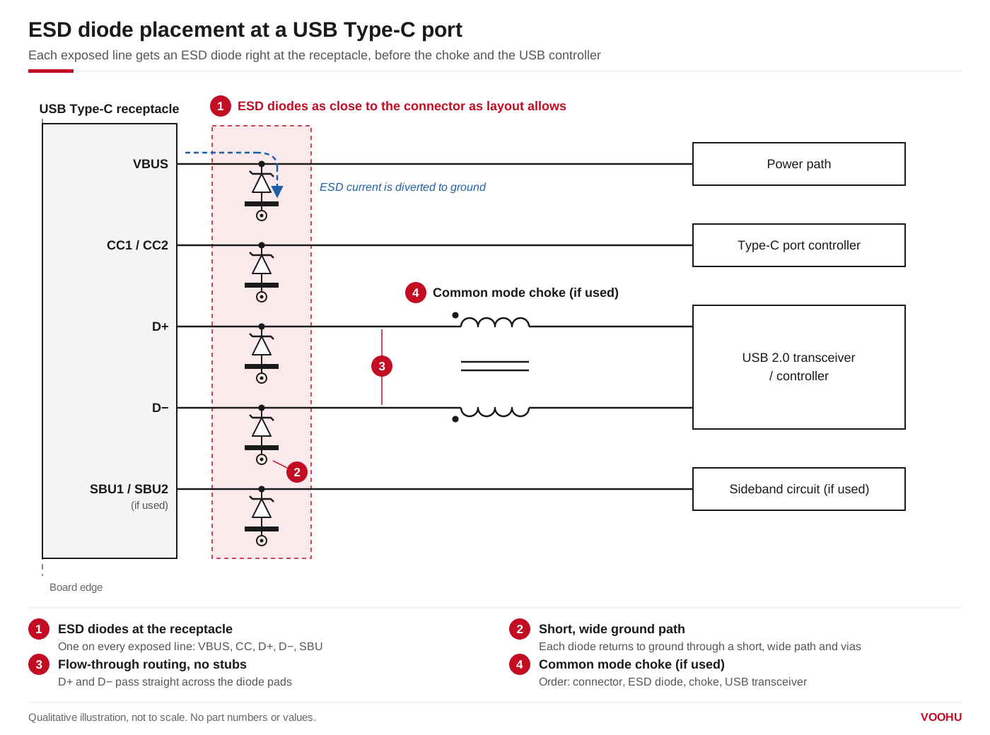
ESD diodes on VBUS, CC, D+, D− and SBU, placed at the USB Type-C receptacle before the common mode choke and the USB controller. Qualitative illustration.
FAQ
Q1: Is ESD protection necessary on a USB port?
On any USB port a user can touch, yes in practice. USB controller pins typically carry component-level ESD ratings for handling during assembly, far below the energy of the system-level IEC 61000-4-2 discharges a finished product is tested with; the diode at the connector takes that strike. An internal port that is never exposed after assembly may not need one.
Q2: Which ESD diode should I use for USB 2.0?
One with a working voltage of at least 3.3 V, line-to-ground capacitance below about 4 pF (TI's guideline for 480 Mbit/s), a clamping voltage below the transceiver's absolute maximum rating and an IEC 61000-4-2 rating that meets your test plan. VOOHU's WHALD03G4U, whose datasheet lists USB 1.1/2.0/OTG, has 0.6 pF typical line-to-ground capacitance.
Q3: Unidirectional or bidirectional ESD diode on USB?
USB 2.0 D+ and D− stay between ground and about 3.3 V, so either type works if its working voltage covers the signal. A unidirectional part clamps a negative strike at about one diode drop below ground, which is usually lower than the negative clamp of a bidirectional part. Bidirectional parts are chosen for lines that may be driven below ground. The datasheet of each part states its configuration.
Q4: Does USB-C need ESD protection on VBUS?
Yes. VBUS is exposed like the data pins and also sees plug and unplug transients; TI notes that inductive ringing can briefly take a 20 V line to 50 V. Choose a working voltage at or above the highest VBUS voltage the port can negotiate (5 V without USB Power Delivery) and a clamping voltage below what the parts on VBUS can withstand.
Get help choosing ESD protection for your USB port
Tell us the connector type (Type-A, Micro-B or Type-C), the lines you need to protect, the highest VBUS voltage, the USB transceiver or hub you use and the ESD level your product must pass, in thesample and support request form. Our FAE team can suggest protection for each line, check working voltage and capacitance against your port and review the placement near the connector. Samples are available for evaluation, and selected parts are free of charge. Our FAE team will be glad to confirm the options for your project.
VOOHU supplies RJ45 and SFP connectors, LAN and PoE transformers, common mode chokes and TVS, ESD, GDT and MOV protection devices from Suzhou, China, to more than 1,500 customers.