Inductor Saturation Current vs Rated Current (Isat vs Irms): Which Do You Check First?
Inductor Saturation Current vs Rated Current (Isat vs Irms): Which Do You Check First?
Saturation current (Isat) and rated current (Irms) limit different things, so a power inductor has to pass both checks. Isat is the DC current at which inductance has fallen by a stated percentage, about 30 % on VOOHU's molded power inductor datasheets. Compare it with the worst-case peak inductor current: the DC load current plus half the ripple. Irms, also called the heating or temperature-rise current, is the DC current that raises the part's temperature by a stated amount, about 40 °C on the same datasheets. Compare it with the RMS inductor current. Which rating runs out first depends on the part and the ripple, so read both definitions on each datasheet. VOOHU's FAE team can check both margins for your converter.
What is saturation current in an inductor?
As DC current rises, the flux density in an inductor's core approaches what the material can carry, its permeability falls and the inductance falls with it. Saturation current is the point on that curve that the manufacturer defines as the limit, stated as a percentage drop from the zero-current inductance, L0.
That percentage is not the same across the industry, or even within one supplier's range. VOOHU's WHYT, WHYTA and WHYTP molded power inductor datasheets define Isat as the DC current that causes L0 to drop approximately 30 %. TheWHPBU-100710Npower bead inductor datasheet defines it at approximately 20 %. Two Isat values taken at different percentages cannot be compared directly.
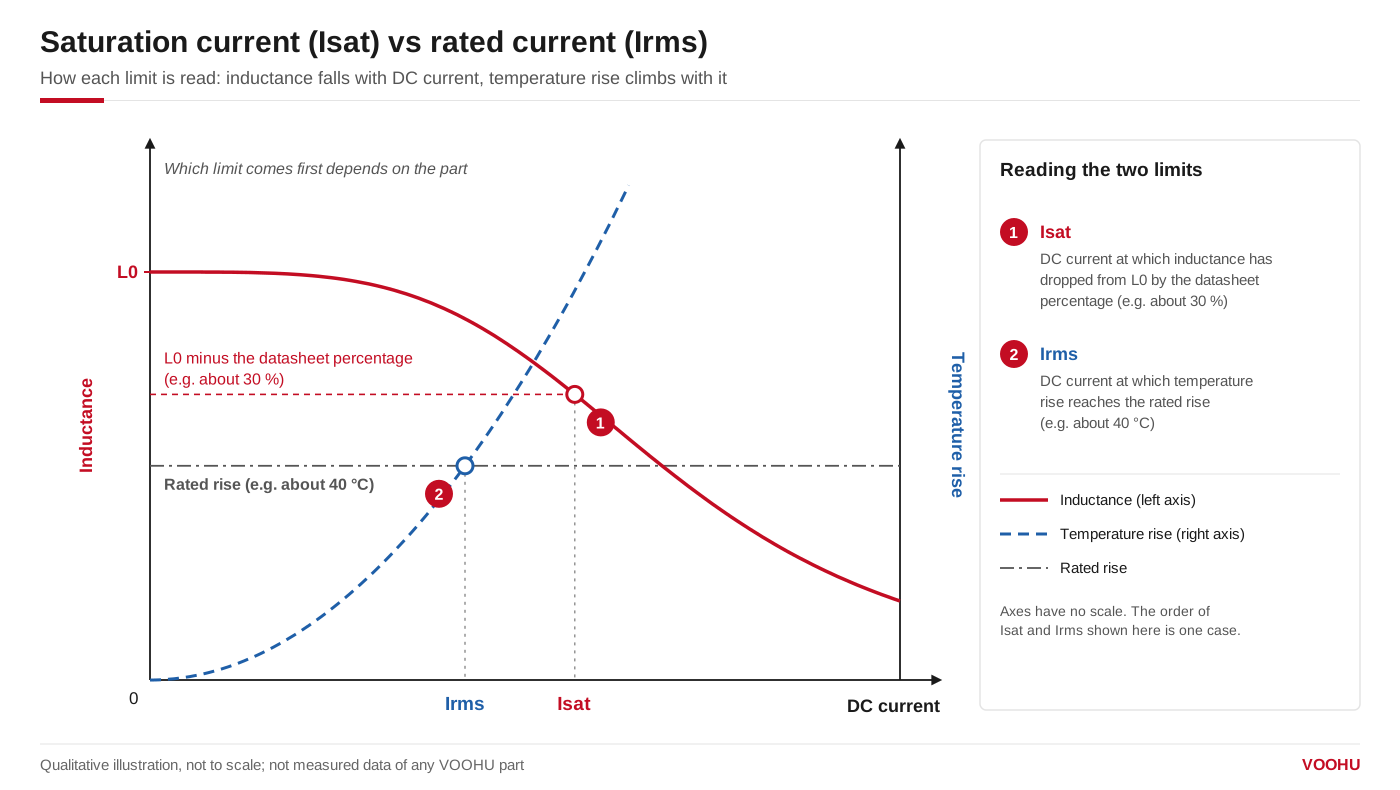
Isat is where inductance has dropped by the datasheet percentage; Irms is where temperature rise reaches the rated rise. Which comes first depends on the part. Illustration only.
What happens if an inductor saturates?
Ripple current follows ΔI = V × t / L. When inductance falls, the current ramps faster, and the higher peak pushes the core further into saturation; on a scope, the ramp steepens near the top of each cycle. The results are extra loss in the switch and inductor, more output ripple and, if the drop is large, current limit trips or overstressed switches. At the defined Isat, inductance is lower by the stated percentage, not gone, but the usual practice is to keep the worst-case peak current below Isat.
What is the rated current (Irms) of an inductor?
The rated current, listed as Irms, heating current or temperature-rise current, is a thermal rating. VOOHU's molded power inductor datasheets define Irms as the DC current that causes an approximate temperature rise of 40 °C, with 25 °C as the reference ambient, and the WHPBU-100710N defines its heating current at about 40 °C as well. Above Irms, inductance does not drop suddenly; the part runs hotter.
The rating is measured with DC, so it covers copper loss in the DC resistance (DCR) but not the core loss and AC winding loss that ripple adds. And the rise adds to the ambient: the molded series datasheets state that the part temperature, ambient plus rise, should not exceed 125 °C and should be verified in the end application. At 85 °C ambient, a 40 °C rise already reaches that limit.
Inductor saturation vs RMS current: which limits your design?
| Check | Saturation current (Isat) | Rated current (Irms) |
|---|---|---|
| What it limits | Peak current in each switching cycle | Continuous heating |
| Compare it with | Worst-case peak current: DC plus half the ripple, at full load, start-up, load steps and current limit | RMS inductor current at maximum continuous load |
| If exceeded | Inductance falls; ripple and peak current rise | The part runs above its rated temperature rise |
With modest ripple, both checks start from the load current and the part decides which runs out first. In the WHYT1250, WHYTA0420 and WHYTP0320 datasheet tables, every value has a typical Isat equal to or above its typical Irms: heating usually sets their continuous current and Isat the headroom for peaks. With large ripple, the peak can still reach Isat first. In the WHPBU-100710N table the order reverses on the higher-inductance values.
Inductor peak current vs saturation current: how to calculate both
For a buck converter, TI'sBasic Calculation of a Buck Converter's Power Stagegives the ripple as ΔIL = (VIN(max) − VOUT) × D / (fS × L), with D the duty cycle at maximum input voltage, and the peak switch current, which the inductor also has to withstand, as ISW(max) = ΔIL / 2 + IOUT(max). For triangular ripple, the RMS current is √(IDC² + ΔIL² / 12).
Suppose a buck converter steps 5 V down to 1.2 V at 4 A, switching at 1 MHz with a 1.0 µH inductor. Ignoring losses, D ≈ 0.24, so ΔIL ≈ 3.8 V × 0.24 / (1 MHz × 1.0 µH) ≈ 0.91 A. The peak current is about 4.46 A and the RMS current about 4.01 A. TheWHYTA0420-1R0M(1.0 µH, Isat 7 A and Irms 6 A typical, DCR 27 mΩ max) leaves room on both checks at its 25 °C reference. Repeat the peak check for start-up and load steps; if the inductor must ride through the converter's current limit, compare Isat with that limit.
Inductor saturation current vs temperature
Isat is usually stated at 25 °C ambient, and with many core materials it falls as the core heats up. Where a datasheet gives a second value, use the one closest to your operating temperature. The WHPBU-100710N datasheet, for example, lists Isat at 25 °C and at 100 °C: 60 A and 50 A typical for theWHPBU-100710N-R22L0(220 nH). Where only the 25 °C value is given, leave margin for temperature and confirm on your board; our FAE team can help you check it.
How to read Isat and Irms on a datasheet
- The definitions.The inductance drop behind Isat, the temperature rise behind Irms and the reference ambient. Compare suppliers by these, not by the numbers alone.
- Typical or minimum.The VOOHU tables in this article give Isat and Irms as typical values (TYP.) and, on the molded series, DCR as a maximum; size your margin accordingly.
- The inductance test conditions.VOOHU's molded series measure L0 at 100 kHz and 1 V with a ±20 % tolerance.
Choosing a VOOHU power inductor by Isat and Irms
All values below are typical Isat and Irms from VOOHU datasheets on the same definitions (L0 drop of about 30 %, temperature rise of about 40 °C, 25 °C ambient). Within each series, higher inductance means lower Isat and Irms and higher DCR.
| Part number | L0 (µH) | DCR max (mΩ) | Isat typ (A) | Irms typ (A) |
|---|---|---|---|---|
| WHYTP0320-1R0M | 1.0 | 38 | 5 | 4 |
| WHYTP0320-4R7M | 4.7 | 200 | 3 | 2.6 |
| WHYTA0420-R47M | 0.47 | 14 | 9.5 | 7.5 |
| WHYTA0420-1R0M | 1.0 | 27 | 7 | 6 |
| WHYTA0420-4R7M | 4.7 | 105 | 3 | 2.8 |
| WHYT1250-R22M | 0.22 | 0.7 | 75 | 50 |
| WHYT1250-1R0M | 1.0 | 2.2 | 35 | 26 |
| WHYT1250-4R7M-E50 | 4.7 | 9 | 20 | 13 |
| WHYT1250-470M-E50 | 47 | 130 | 5.0 | 3.0 |
TheWHYTP0320-1R0M(3.4 × 3.2 × 1.8 mm) suits compact rails where board area is tight, theWHYTA0420-1R0Mpoint-of-load rails of a few amps, as in the example above, and theWHYT1250-R22M and WHYT1250-1R0Mhigh-current rails at 50 A and 26 A typical Irms. For very high current at low inductance, theWHPBU-100710N-R22L0power bead inductor lists 60 A typical Isat at 25 °C on its 20 % definition and a 70 A typical heating current; compare it on those terms.
Filter themolded power inductor selectorby series, or browse theWHYT seriesandhigh-current power bead inductors. Related guides:selection and layout, coil whine, parallelingand, for inductors near sensitive circuits,shielded vs unshielded power inductors.
产品WHPBU-100710N-R22L0
FAQ
Q1: Is an inductor with a lower saturation current than the RMS current any good?
Yes, as long as the worst-case peak current stays below Isat. The ratings come from different tests, so a part can saturate before it gets hot. The WHPBU-100710N-R47M0 (470 nH) lists 20 A typical Isat at 25 °C against a 70 A typical heating current; for a part like this, Isat sets the usable current and the heating rating leaves thermal headroom.
Q2: How do you measure inductor saturation current?
Measure inductance while a DC bias current flows through the part, raising the bias in steps at the datasheet's test frequency and level (100 kHz and 1 V on VOOHU's molded series), until inductance has fallen by the datasheet percentage. Without a bias source, use a pulse test: apply a short voltage pulse and watch the current ramp on a scope. Since L = V / (di/dt), the ramp steepens as the core saturates. Keep pulses short so the part does not heat.
Q3: Is there a rule of thumb for current derating of inductors?
No single number fits every part, because suppliers define Isat and Irms differently and often give typical values. A safer method: calculate the worst-case peak and RMS currents, compare them with Isat at your operating temperature and with Irms, check that ambient plus rise stays below the maximum part temperature, and then measure the inductor's temperature and current waveform on the board.
Get help checking Isat and Irms for your converter
Send us the input and output voltages, load current, switching frequency, the inductance you have in mind and the ambient temperature in thesample and support request form. Our FAE team can calculate the peak and RMS currents, suggest molded power inductors with suitable Isat and Irms margins and check the footprint. Samples are available for evaluation, and selected parts are free of charge. Our FAE team will be glad to confirm the options for your project.
VOOHU supplies RJ45 and SFP connectors, LAN and PoE transformers and common mode chokes from Suzhou, China, to more than 1,500 customers.
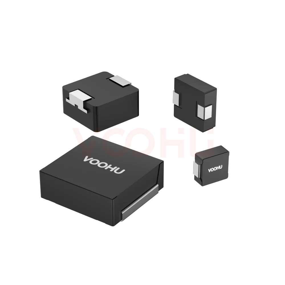 WHYTA0420 series Inductance Value 0.1-10uH DCR 4-282mΩ IRMS 1.6-13A ISAT 2-22A Integrated Molded inductor
> View Details
WHYT1250 series Inductance Value 0.22-47uH DCR 0.7-130mΩ IRMS 3-50A ISAT 5-75A Integrated Molded inductor
> View Details
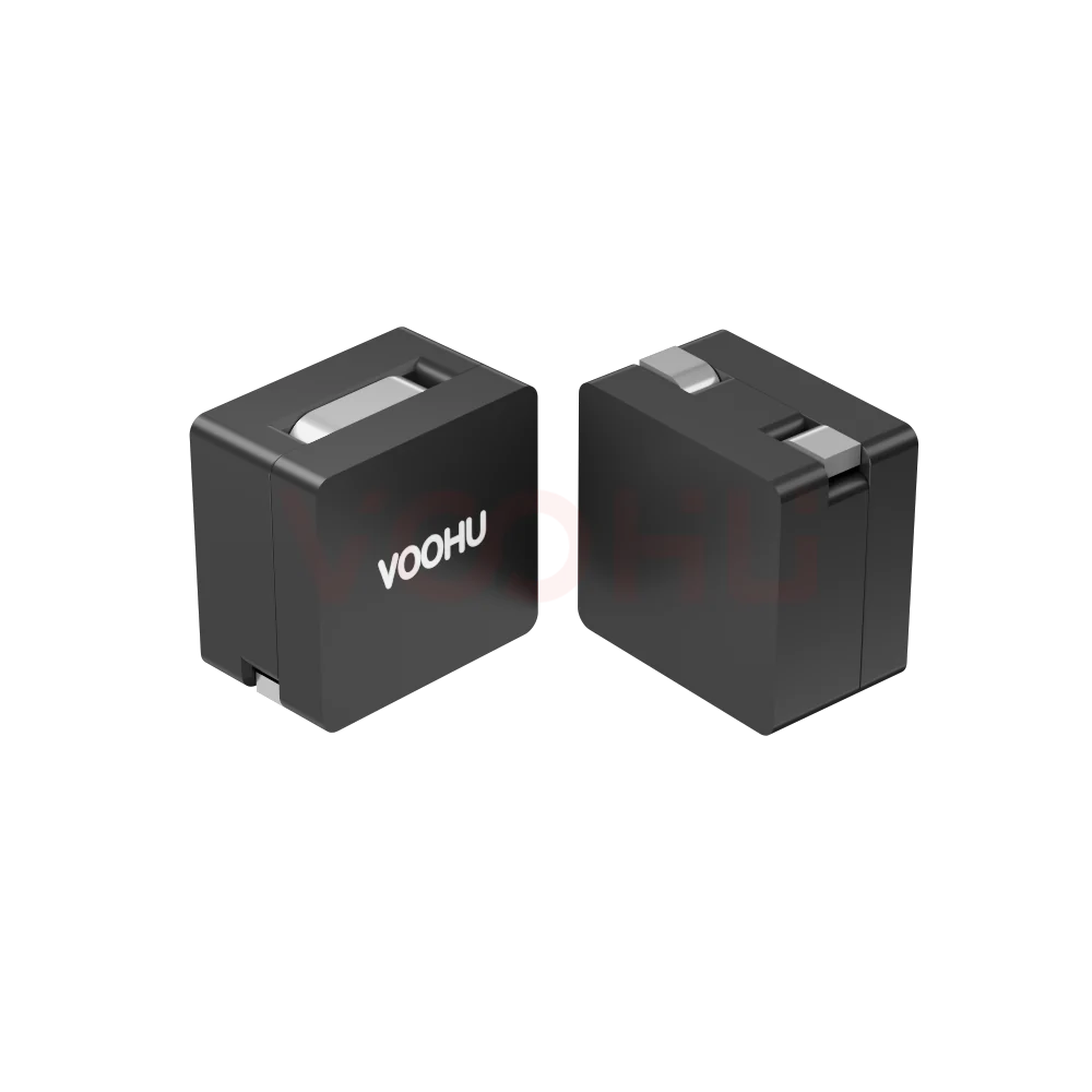 WHPBU-100710N-R22L0 Initial Inductance:220nH Tolerance: 15 (±%) DCR0.18 ± 10%mΩ Heating Current (Amps) (typ)70 Combined Inductor
> View Details
WHYTP0320 series Inductance Value 0.33-10uH DCR 21-422mΩ IRMS 1.4-8A ISAT 1.6-10A Integrated Molded inductor
> View Details