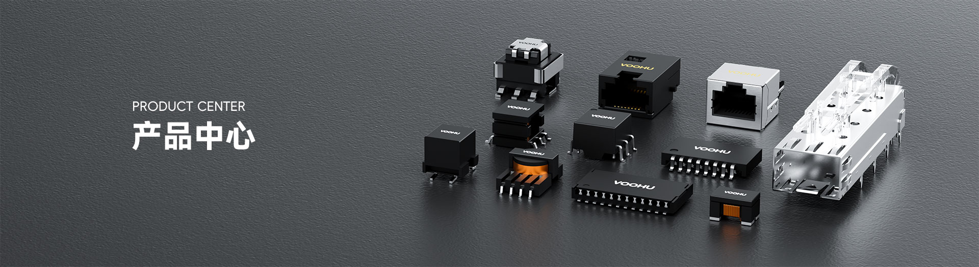
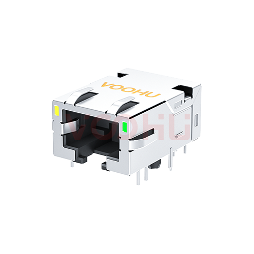
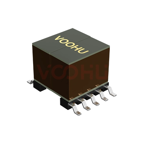
WHSQ48802C2 Dual Ports SMD 2.5G/5G PIN48 4PPoE LAN Transformer


Request a Quote
Leave your details and we will send a tailored volume quote.
Our sales team will contact you within 1 business day.
Contact Sales
Reach our sales team for pricing and lead time.

Submitted
We have received your request. Our sales team will contact you within 1 business day.


For technical assistance, pleaseclick the button below to add customer service or visit the sample request pageto fill out the form. We will serve you as soon as possible.
Technical Support Email: fae.thorne@voohu.cn Phone: +86 400-1048-018
For more details, please visit theDownload Centerto get documents or click the button below to add customer service. We will serve you as soon as possible.


For purchases and small-volume orders, please contact our sales team. We support VAT general/special invoices with a convenient and efficient process.
For technical assistance or sample requests, pleaseclick the button belowto add customer service orvisit the sample request pageto fill out the form. We will serve you as soon as possible.
Customer Service Email: song.lei@voohu.cn Phone: +86 180 2130 1120
The WHSQ48802C2 specifies insertion loss, return loss, crosstalk and common-mode rejection only to 200 MHz, where most parts in this range are specified to 250 MHz.What that boundary means in practice is the scope of your sign-off evidence: a link margin analysis can cite the WHSQ48802C2 limits up to 200 MHz and no further, and figures taken from other parts in the range cannot be used to fill the gap.
Where the project needs limits out to 250 MHz, theWHSQ48802C1is the direct alternative to the WHSQ48802C2, in the same package, with the same pin assignment and the same PoE rating.
Size the copper of the WHSQ48802C2 for 1200 mA per magnetic channel.The datasheet states PoE Support 60W and gives the current per channel: each channel supports 1200 mA of DC balance current. Route the eight centre-tap paths as eight balanced paths of that rating and calculate the width from your actual copper thickness and permitted rise.
The datasheet publishes no port-level total for the WHSQ48802C2, so keep the per-channel figure as the copper basis and route each port's four paths as its own group. No wattage available at the PD can be derived from the current – 60 W is the device-side rating.
Choose on the current each channel has to carry: the WHSQ48802C2 carries 1200 mA per magnetic channel at a stated PoE Support 60W, while theWHSQ48002P1carries 360 mA per channel at a stated PoE Support 30W.Both operate from -40 °C to +85 °C with the temperature rise included and share the same isolation test.
They do not share a footprint: the WHSQ48802C2 stands 11.70 mm tall against 7.50 mm for the WHSQ48002P1, and neither the body outline nor the pad layout is common, so check each against your board and enclosure. Both are listed in the2.5G/5G BASE-T range.