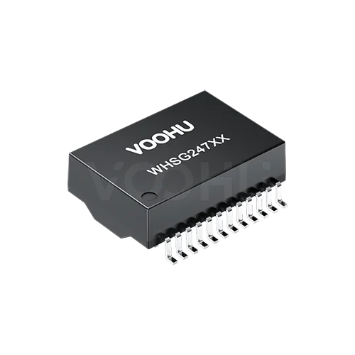
Pulse H6096NL Alternative: VOOHU WHSG24701AG Comparison
On paper the Pulse H6096NL and the VOOHU WHSG24701AG line up closely, and the WHSG24701AG is a functional alternative to the H6096NL — verify with samples in your design. Each part puts one gigabit port's four channels into a 24-lead, 1.27 mm-pitch SMD body, the pin numbering and names agree, and the datasheets share three headline figures: OCL of 350 µH or more with 8 mA of DC bias, a 1500 V, 60 s hipot, and operation from 0 to 70 °C. The difference is inside the package. The Pulse schematic puts a three-wire choke ahead of the transformer, on the chip side of each channel, so the TCT center tap runs through it. VOOHU puts a two-wire choke on the line side and takes MCT from a center-tapped winding after it. That changes the circuit your center-tap pins connect to, and it is worth an EMC comparison before release.
[Product] WHSG24701AG
H6096NL vs. WHSG24701AG: the two datasheets side by side
Every value below comes from one public document per part. For Pulse that is the H6096NL datasheet, revision A (drawing PS-2473.001-A): notes on sheet 1, schematic and electrical table on sheet 2, outline and suggested pads on sheet 3. Pulse dimensions its drawings in inches with millimetres in brackets, and the table uses the millimetre values. For VOOHU it is the WHSG24701AG datasheet, revision A0, with outline, suggested pads and schematic on page 1 and the electrical list, items C.1 through C.11, on page 2. Lengths are in millimetres. A value marked derived is calculated from two printed dimensions; not stated means the datasheet does not give it.
| Parameter | Pulse H6096NL (datasheet rev. A) | VOOHU WHSG24701AG (datasheet rev. A0) |
|---|---|---|
| Description / data rate | "MDL, SIN, 1GP, 1:1, SM, TU"; "Meets IEEE 802.3 specification" (sheet 2) | 100/1000 BASE-T (p1 title block) |
| Order inside each channel | Chip-side three-wire common mode choke carrying TD+, TCT and TD−, then a 1:1 transformer; MCT taken from the line-side winding's center tap (sheet 2 schematic) | Chip-side transformer with TCT at its center tap, then a line-side two-wire common mode choke, then a center-tapped winding across MX+ and MX− whose midpoint is MCT (p1 schematic) |
| Leads / pitch / first to last | 24; 1.27; 13.97 (sheet 3) | 24; 1.27 ± 0.20; 13.97 ± 0.20 (p1) |
| Pin names | TCT1, TD1+, TD1− on pins 1–3 through TCT4, TD4+, TD4− on 10–12; MCT1, MX1+, MX1− on 24–22 through MCT4, MX4+, MX4− on 15–13 (sheet 2) | Same names on the same pins (p1) |
| Body length × width | 18.16 ± 0.25 × 12.2 (sheet 3) | 17.55 ± 0.50 × 12.20 ± 0.50 (p1) |
| Width across leads | 16.00 +0.25 / −0.38 (sheet 3) | 16.00 ± 0.50 (p1) |
| Height | 6.60 (sheet 3) | 6.00 ± 0.50 (p1) |
| Standoff | 0.25 (sheet 3) | 0.25 ± 0.10 (p1) |
| Lead width / foot length | 0.51 / 1.43 (sheet 3) | 0.50 ± 0.10 / 1.10 ± 0.15 (p1) |
| Coplanarity | 0.10 (sheet 3) | 0.100, 24 surfaces (p1) |
| Suggested pad width | 0.76 (sheet 3) | 0.76 typ (p1) |
| Suggested pads, inner edge to inner edge | 12.70 (sheet 3) | 12.70 typ (p1) |
| Suggested pads, outer edge to outer edge | 16.51 (sheet 3) | 16.60 typ (p1) |
| Suggested pad length | About 1.91, derived | About 1.95, derived |
| Turns ratio | 1:1 ± 3% (sheet 2) | 1CT:1CT ± 5% (p2, C.4) |
| OCL | Media side, 0 to +70 °C: 350 µH min at 100 kHz, 100 mVrms, 8 mA DC bias; 120 µH min at 100 kHz, 100 mVrms, 19 mA DC bias (sheet 2) | 350 µH min at 100 kHz, 0.1 V, 8 mA DC bias (p2, C.1); at 19 mA: not stated |
| Leakage inductance | Not stated | 0.5 µH max at 100 kHz, 0.1 V (p2, C.2) |
| DCR | 0.30 Ω typ, 1/2 winding; balance ± 0.05 Ω max, center tap symmetry (sheet 2) | 1400 mΩ max (p2, C.3) |
| Insertion loss | −1.2 dB max at 100 kHz; −0.2 − 0.002 × f^1.4 dB max, 1–125 MHz (sheet 2) | −1.1 dB max, 1–100 MHz (p2, C.5) |
| Return loss | Z out = 100 Ω ± 15%: −16 dB min, 1–40 MHz; −10 + 20 × log10(f/80 MHz) dB min, 40–100 MHz (sheet 2) | −18 dB min, 1–30 MHz; −14.4 dB at 40 MHz; −13.1 dB at 50 MHz; −12 dB, 60–80 MHz; −10 dB at 100 MHz (p2, C.6) |
| Crosstalk | Adjacent channels: −50 dB min at 1 MHz; −55 + 22 × log10(f/10) dB min, 10–100 MHz (sheet 2) | −30 dB min, 1–100 MHz (p2, C.7) |
| Common mode rejection | −50 dB min at 2 MHz; −15 + 20 × log10(f/200) dB min, 30–200 MHz (sheet 2) | −30 dB min, 1–100 MHz (p2, C.8) |
| Isolation (hipot) | 1500 Vrms min, 60 s (sheet 2) | 1500 VAC, 1 mA, 60 s (p2, C.9) |
| Operating temperature | 0 to 70 °C (sheet 2) | 0 to +70 °C (p2, C.10) |
| Storage temperature | −20 to +125 °C (sheet 1, note 3) | −40 to +85 °C (p2, C.11) |
| PoE rating | Not stated | Not stated in the datasheet; product page: Not PoE rated |
| MSL / soldering | J-STD-020 Level 1; J-STD-075 R7, 245 °C max (sheet 1, note 4) | Not stated |
| Packaging | T suffix = tape and reel (sheet 1, note 5) | 330 mm reel, 350 pcs per reel (p2, D) |
Common mode choke on the chip side or the line side: how the H6096NL and WHSG24701AG are built
Trace channel A from the PHY pins to the cable pins on each schematic. On the H6096NL, TD1+ on pin 2, TCT1 on pin 1 and TD1− on pin 3 enter a three-wire common mode choke together and only then reach the 1:1 transformer. The middle wire of that choke ties TCT1 to the midpoint of the transformer's chip-side winding, and the midpoint of the line-side winding comes straight out as MCT1 on pin 24. On the WHSG24701AG, TD1+ and TD1− go directly into the transformer, and TCT1 is that transformer's own chip-side center tap. The line side of that transformer feeds a two-wire common mode choke, and after the choke a center-tapped winding sits across MX1+ and MX1−; its midpoint is MCT1 on pin 24. The pin names stay the same. The choke, though, has moved to the other side of the transformer and gone from three wires to two, and the other three channels repeat the same pattern.
Your schematic notices this at pins 1, 4, 7 and 10, where the PHY's center-tap network lands, and that network depends heavily on the PHY. Texas Instruments' application note SDAA089 (section 3.2) shows the spread within a single vendor's 10/100 PHYs: for the current-mode DP83848 it recommends shorting the center taps between channels and pulling them up to the 3.3 V analog supply with 100 nF of decoupling per channel, while for the voltage-mode DP83826A it recommends only 2 nF of decoupling per center tap. Gigabit PHYs set out their own requirement in their datasheets. On the H6096NL, whatever you connect to TCT reaches the transformer through the middle wire of the chip-side choke; on the WHSG24701AG it connects straight to the transformer's chip-side center tap. Neither datasheet says what that does to your PHY's bias or noise. So open the center-tap section of your PHY datasheet and reference design, check whether it asks for a particular magnetics arrangement, keep the TCT network as the PHY vendor specifies it, and redraw the library symbol with the choke on the line side so the schematic matches page 1 of the WHSG24701AG datasheet.
Moving the choke to the line side: what EMC and certification engineers should re-run
For EMC and certification, treat this as a change of magnetics, not a like-for-like swap, even though every pin name matches. The MCT pins, 24, 21, 18 and 15, usually carry the Bob Smith termination, and on the WHSG24701AG that network now connects at the midpoint of a winding that follows the choke, rather than at the transformer's own center tap; our guide to why Ethernet ports fail testing covers that termination in more detail. The datasheet limits will not predict the outcome for you: Pulse specifies common mode rejection at 2 MHz and as a formula from 30 to 200 MHz, VOOHU as one minimum from 1 to 100 MHz, so the two cannot be drawn on the same curve. Measure instead. Use the H6096NL build as the baseline and repeat radiated and conducted pre-scans with the link up at each speed your product negotiates, using the cable type and length from your original report. If your product standard includes ESD, EFT or surge on the Ethernet port, add those, because the network that faces the cable has changed. Whether the result needs a formal re-test or only a technical file update is a question for your test laboratory and certification scheme, not for either datasheet.
Does the WHSG24701AG list an OCL at 19 mA DC bias like the H6096NL?
No. Pulse prints two OCL minimums for the media side over 0 to +70 °C, both at 100 kHz and 100 mVrms: 350 µH with 8 mA of DC bias and 120 µH with 19 mA. VOOHU prints one, 350 µH minimum at 100 kHz, 0.1 V and 8 mA DC bias, so at the 8 mA point the two parts are specified under the same condition. A 19 mA figure is not stated for the WHSG24701AG. Whether that matters depends on why the 19 mA line was in your design review in the first place. If nobody referenced it, nothing changes. If your design puts DC through the line-side windings at that level, or a reviewer used 120 µH as a sign-off criterion, ask us for WHSG24701AG data at your actual bias before you approve the part. And do not read the Pulse 19 mA line as a PoE rating: it is an inductance test condition, and neither datasheet states PoE.
H6096NL land pattern and outline: 16.51 vs. 16.60 mm across the pads, 6.60 vs. 6.00 mm tall
For layout, the two suggested patterns agree on everything along the rows: every pad is 0.76 mm wide, the pitch is 1.27 mm, and the first-to-last span is 13.97 mm. Across the rows, the inner edges are 12.70 mm apart on both drawings. The outer edges differ by 0.09 mm, 16.51 mm on the Pulse sheet and 16.60 mm on the VOOHU sheet, which makes the pads about 1.91 mm and 1.95 mm long and puts the VOOHU pad edge about 0.045 mm further out on each side (all derived). Both parts measure 16.00 mm nominal across the leads, and with the 1.10 mm VOOHU foot that places the feet between about 13.80 and 16.00 mm, inside the existing copper (derived). Check that at the tolerance limits rather than at nominal: overlay the WHSG24701AG outline at 15.50 and 16.50 mm across the leads on your H6096NL pads, then let the first-article build show the toe and heel fillets. No written FAE confirmation covers the Pulse pattern, so keep the release decision with that build.
The outline gets smaller in two directions. The VOOHU body is 17.55 ± 0.50 mm long against 18.16 ± 0.25 mm for Pulse, and 6.00 ± 0.50 mm tall against 6.60 mm nominal. Even at the top of its tolerance, 6.50 mm, the WHSG24701AG stays below the H6096NL's nominal height, and at its 18.05 mm maximum length it still fits inside a courtyard or silkscreen drawn around the 18.16 mm Pulse body (both derived). A shield, light pipe or housing rib sized for the Pulse part therefore keeps its clearance, and the existing outline can stay for the trial. The width is 12.2 mm on the Pulse drawing and 12.20 mm on the VOOHU drawing. For the EMS, the change worth making is in the placement program: update the body size to 17.55 × 12.20 × 6.00 mm so vision recognition and nozzle height use the part that is actually on the reel.
H6096NL to WHSG24701AG: a swap checklist by role
| Role | What to verify | Evidence to keep |
|---|---|---|
| Hardware design | Center-tap (TCT) network and any magnetics requirement in your PHY datasheet and reference design; TCT network kept as the PHY vendor specifies | Design review note naming the PHY document and section |
| Hardware design | Whether the Pulse 120 µH at 19 mA line was used in your review; if it was, WHSG24701AG data at your bias requested from VOOHU | Written answer on file, or "not used" recorded |
| Hardware design | Library symbol: two-wire choke on the line side, MCT from the line-side center-tapped winding | Symbol matches WHSG24701AG datasheet page 1 |
| EMC / certification | Radiated and conducted pre-scans at each negotiated speed against the H6096NL baseline; port ESD, EFT or surge if your standard requires them | Side-by-side results and the test laboratory's re-test decision |
| Layout | WHSG24701AG outline at 15.50 and 16.50 mm across the leads on the 12.70 / 16.51 mm pads; clearance above the part against 6.50 mm | Pad set and keep-out confirmed for the trial build |
| SMT / EMS | Placement program body size 17.55 × 12.20 × 6.00 mm; first article toe and heel fillets and bridging on all 24 joints | First article signed off |
| Quality | Turns ratio ± 5%, DCR 1400 mΩ max, hipot 1500 VAC, 1 mA, 60 s; MSL and reflow conditions received from VOOHU in writing before the first reel reaches the line | Inspection sheet and moisture-control entry written to the WHSG24701AG datasheet |
| Purchasing | Alternate entry made against H6096NL, not HX6096NL, with the condition "non-PoE gigabit port, after EMC comparison" | Entry released after sample approval |
Where the WHSG24701AG fits
The WHSG24701AG is for a single gigabit port without power on the data pairs (the product page marks it Not PoE rated), where the PCB already carries a wide-body footprint with 24 leads at 1.27 mm and the equipment runs within 0 to +70 °C, the same range the H6096NL datasheet gives. If the same product uses other Pulse transformers you want to second-source, our HX5120NL evaluation works through another pair.
[Solution] /solution-ethernet/
FAQ
Q1: What is an equivalent for Pulse H6096NL?
The VOOHU WHSG24701AG is a functional alternative to the Pulse H6096NL — verify with samples in your design. The two datasheets agree on a 24-lead SMD body with 1.27 mm pitch and matching pin names, and both give at least 350 µH of OCL under 8 mA DC bias, a 60-second 1500 V hipot and an operating range of 0 to 70 °C. The H6096NL has its common mode choke on the chip side and the WHSG24701AG on the line side, so review the center-tap circuit against your PHY and compare EMC results.
Q2: Is the H6096NL the same part as the HX6096NL?
Do not assume so. They are separate Pulse part numbers, and this comparison is based only on the H6096NL datasheet, revision A. Distributor listings for the two can turn up side by side in a search, so check the exact number on your BOM and on the datasheet you hold before you use any value in this article.
Q3: Is the Pulse H6096NL PoE rated?
Its datasheet does not state a PoE rating. It does list a second OCL minimum, 120 µH at 19 mA DC bias, but that is an inductance test condition, not a PoE current rating. The WHSG24701AG datasheet does not state PoE either, and the WHSG24701AG product page marks it Not PoE rated, so this pairing applies to gigabit ports without power on the data pairs.
Q4: Can the WHSG24701AG go on the H6096NL land pattern?
Plan it as a trial. Both suggested patterns use 0.76 mm pads on a 1.27 mm pitch with inner edges 12.70 mm apart, and the outer edges are 16.51 mm on the Pulse drawing and 16.60 mm on the VOOHU drawing. Overlay the WHSG24701AG leads at 15.50 and 16.50 mm across on your pads and confirm with a first-article build; no written FAE confirmation covers the Pulse pattern yet.
Check your H6096NL port with WHSG24701AG samples
When you request WHSG24701AG samples, include the PHY part number, the schematic from the PHY center-tap pins through the transformer to the RJ45 with the TCT network and the Bob Smith termination visible, and the land pattern from your H6096NL board. Samples are available for evaluation, and selected parts are free of charge. Our FAE team will be glad to confirm the options for your project. Our FAE team can suggest suitable parts and help check the design — here, how the TCT network on pins 1, 4, 7 and 10 sits against a transformer without a chip-side choke, whether your review relied on the 19 mA OCL figure, and where the WHSG24701AG leads land on the 16.51 mm Pulse land pattern.
VOOHU supplies RJ45 and SFP connectors, LAN and PoE transformers and common mode chokes from Suzhou, China, to more than 1,500 customers.
Other gigabit, 24-pin, 1.27 mm-pitch transformers without a PoE rating are listed next to it in our LAN transformer selector, already filtered that way.
Related product: WHSG24701AG. Its datasheet describes a one-port 100/1000BASE-T SMD transformer with 24 leads on 1.27 mm; the body measures 17.55 × 12.20 × 6.00 mm nominal, OCL is 350 µH or more under 8 mA DC bias, each channel carries a two-wire choke on the line side, the hipot is 1500 VAC held for 60 s, and it runs from 0 to +70 °C with no PoE rating.