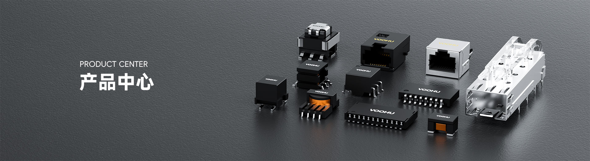
WHSG5001-2 G 100/1000Base-T Double mouth 50PIN Ethernet transformer


Request a Quote
Leave your details and we will send a tailored volume quote.
Our sales team will contact you within 1 business day.
Contact Sales
Reach our sales team for pricing and lead time.

Submitted
We have received your request. Our sales team will contact you within 1 business day.


For technical assistance, pleaseclick the button below to add customer service or visit the sample request pageto fill out the form. We will serve you as soon as possible.
Technical Support Email: fae.thorne@voohu.cn Phone: +86 400-1048-018
For more details, please visit theDownload Centerto get documents or click the button below to add customer service. We will serve you as soon as possible.


For purchases and small-volume orders, please contact our sales team. We support VAT general/special invoices with a convenient and efficient process.
For technical assistance or sample requests, pleaseclick the button belowto add customer service orvisit the sample request pageto fill out the form. We will serve you as soon as possible.
Customer Service Email: song.lei@voohu.cn Phone: +86 180 2130 1120
WHSG5001-2G 1 foot is `TD1+ ' , 2 foot is the central `TCT1 ' and 3 foot is `TD1 ' , arranged in groups of each of the three feet that follow; 1– 25 feet are `TCT '/`TD ' , 26&ndash on the side of the chip; 50 feet are on the side of the webline `MCT '/`MX ' , 13 of which do not correspond to 38 feet. Special attention needs to be paid to the fact that in the model of the same 50 PIN, the same welding set, one foot and two pairs of feet correspond to the other (the foot is the centre head). Welds are the same and the devices can be pasted, but the lines are not universal, so please move your own drawings to the target model.
specifications and therefore cannot be selected for the PoE device, both of which are supplied locally. The centre's head is only used as a point of reference for communication and commories. The same 50 PIN welds have models with PoE current labels that can be replaced at the selection stage when grid power is required; — but not all of the foot positions of the people are universal if the foot is allocated together.
Select the shape that the PCB can give: WHSG 50001-2G body 27.80 & times; 7.60 mm, with quotes 1080 mm, high 8.35 mm; 48 PIN stickers with double mouths 2780 & Times; 12.20 mm, with quotes 15.20 mm, high 7.50 mm Max. The two are the same length, 50 PINs are narrower but higher, 48 PINs are wider and shorter. 48 PIN, 50 PIN, when horizontal space tension on board. Two sealed welds are not common to each other.