Late in a DC-DC design, the load current often turns out higher than planned. The molded inductor runs hotter than expected, and the height limit rules out a taller part. The quickest idea is to place a second identical inductor next to the first and put the two in parallel: each carries half the current, so the temperature rise should drop.
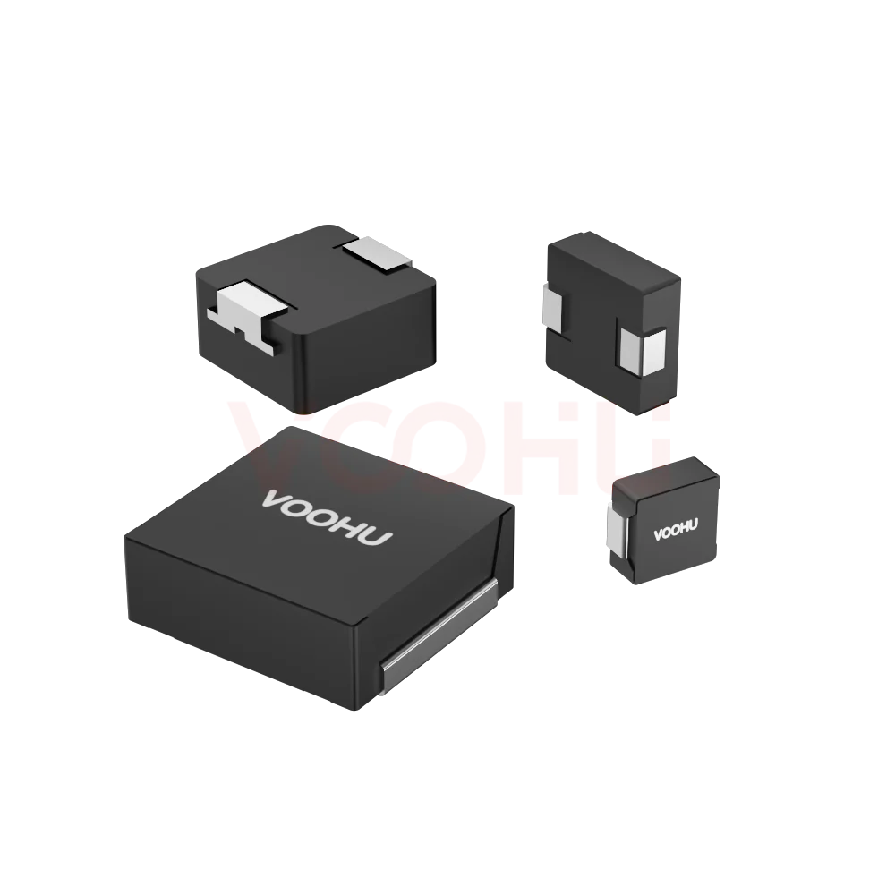
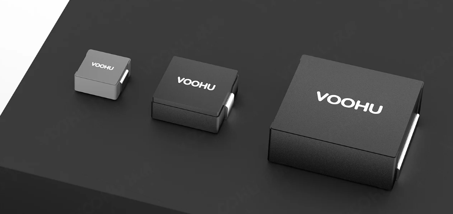
That idea is only half right. Two inductors can be paralleled, but the inductance halves and the ripple current grows. The current also does not split evenly by itself: DCR tolerance and PCB trace resistance decide which part carries more. In low-inductance, low-DCR ratings, one extra centimetre of copper can make one inductor carry twice the current of the other. Using the selection tables for VOOHU molded inductors in the WHYT series, this article explains when paralleling works, how to do it, and when a single larger part is the better choice.
#1. Short answer: yes, but inductance halves and current does not split evenly
Three things happen at once when two inductors are paralleled.
First, the equivalent inductance falls. Two equal inductors in parallel give half the inductance of one; unequal values combine as L1×L2/(L1+L2). Lower inductance means a larger total ripple current in the converter.
Second, DC current divides by resistance. In steady state both branches see the same voltage, so DC current is inversely proportional to each branch's total resistance. That resistance includes the inductor DCR plus pads, copper and vias. The branch with less resistance carries more current.
Third, ripple current follows each inductor's own inductance. Both inductors see the same voltage, so each one's ripple depends only on its own inductance. The part with slightly lower inductance has more ripple and a higher peak current, and it approaches ISAT first.
So "two in parallel doubles the current rating" holds only in the ideal case. A real design derates each part for imbalance and then compares the result with simply moving to a larger inductor.
#2. Inductance halves: total ripple doubles unless each part has twice the inductance
Take a common buck converter: 12 V in, 3.3 V out, 500 kHz, originally using one 2.2 µH inductor. Ripple current is ΔI = (Vin − Vout) × D / (L × f). With D ≈ 3.3/12 = 0.275, a single 2.2 µH part has about 2.2 A of ripple.
Add a second 2.2 µH in parallel and each inductor still carries about 2.2 A of ripple, because the voltage across each is unchanged. The two ripple currents are in phase and add, so the total ripple into the output capacitors becomes about 4.4 A. With the same capacitors, output voltage ripple nearly doubles. The controller's peak current limit sees the total current, so it also trips earlier.
To bring total ripple back to the original level, each part needs roughly twice the inductance, for example two 4.7 µH inductors. The catch is that within one size series, higher inductance means more turns, so DCR generally rises and IRMS falls. The DCR and IRMS ranges in the VOOHU selection tables follow this pattern: the lowest inductance rating has the lowest DCR and highest IRMS, and the highest rating is the opposite. Two 4.7 µH parts in parallel are therefore not automatically much stronger than one 2.2 µH part. Check the actual DCR and IRMS of both inductance ratings in the datasheet.
#3. DC divides by resistance: DCR tolerance decides who carries more
Inductors of the same part number still have DCR tolerance, and datasheets usually give a typical and a maximum value. Even two parts from the same lot will not match exactly. Here is a worked example.
Assume the two branches have total resistances of 10 mΩ and 12 mΩ (a 20% difference covering DCR tolerance and routing), with 12 A total output current. Current is inversely proportional to resistance: the 10 mΩ branch takes 12 × 12/(10+12) ≈ 6.5 A and the 12 mΩ branch about 5.5 A. By I²R, losses are about 0.43 W and 0.36 W.
A 20% resistance difference produces roughly ±9% current imbalance. If IRMS is checked assuming each part carries exactly half, the heavier part will exceed its expected temperature rise. A safer method is to calculate the heavier branch current using the worst-case DCR combination, then check that current against a single part's IRMS and ISAT.
Copper resistance rises with temperature (about 0.39%/°C). The part carrying more current runs hotter, its DCR rises, and some current shifts back to the other part, so DC sharing is partly self-balancing. That balance is paid for with a temperature difference, though, so the hotter part stays hotter. It is not a current-sharing method you can rely on.
#4. The counter-intuitive part: at low inductance, PCB copper outweighs the inductor DCR
Many designers watch DCR tolerance and ignore the routing. For 1 oz (35 µm) copper, sheet resistance is about 0.5 mΩ per square, meaning a square patch of copper of any size measures about 0.5 mΩ end to end. A trace 5 mm wide and 10 mm long is two squares, about 1 mΩ.
Now look at the VOOHU tables: the WHYT1040 series DCR range is 0.65–340 mΩ, the WHYT1250 series is 0.7–130 mΩ, and the WHYT1050 series is 0.8–290 mΩ. The low-inductance ratings are already below 1 mΩ, the same order as an ordinary piece of copper.
Example: two inductors with 1 mΩ DCR each are paralleled, and one has an extra 10 mm of output copper (about 1 mΩ more). The branches become 1 mΩ and 2 mΩ, and current divides 2:1. At 30 A total, one part carries 20 A and the other only 10 A. At this point inductor DCR tolerance hardly matters; the layout sets the current split.
The lower the inductance and DCR, the harder it is to share current. In high-current, low-inductance designs (for example below 1 µH at tens of amps), two inductors tied to the same switch node are not dependable. Routing differences only become minor once inductance is higher and DCR is in the tens of milliohms.
#5. Saturation is not shared: the part that reaches ISAT first drops first
ISAT is the current at which inductance has fallen by a specified percentage; the percentage is defined in the datasheet. In parallel, each inductor's peak current equals its own DC share plus half its own ripple.
The worst case is when both deviations land on the same part: lower branch resistance gives it more DC, and lower inductance gives it more ripple. Its peak current will be clearly higher than the other part's. Once it nears ISAT, inductance falls, ripple grows further and the peak rises again.
Molded inductors use a metal powder core, so saturation is gradual rather than abrupt as in ferrite, which is one of their strengths. Gradual still has consequences: falling inductance raises ripple and loss, and the temperature follows. Check ISAT using the heavier branch's DC current plus its ripple, at maximum operating temperature, not total current divided by two.
#6. Two small parts or one larger part? Compare with the VOOHU series table
When height is limited, the better route is usually a larger footprint at the same height. The VOOHU WHYT series is organised by footprint and height, with several footprints available at each height. The table below is taken from the website selection table; body area is length × width and excludes pad extension and spacing.
A few points stand out.
First, two 7.0 × 6.6 mm parts have about 92 mm² of body area. Add the spacing between them and symmetric routing, and the real board area is close to one 11.5 × 10 mm part (115 mm²).
Second, at the same height the larger series reaches lower DCR and higher IRMS. At 3.8 mm, for example, the WHYT0640 IRMS range tops out at 17 A, while the WHYT1040 reaches 45 A.
Third, the upper ends of these ranges come from the lowest inductance rating, so they are for screening only. For a real comparison, look up DCR, IRMS and ISAT for both options at the inductance you need, then apply the imbalance derating from section 3 to the parallel option.
A single larger inductor has one current path, so there is no sharing problem and half as many solder joints. In most cases it is the more robust choice.
#7. When current really must be shared: use a multiphase buck, one inductor per phase
If the current is beyond what one inductor can carry, the right answer is not two inductors on one switch node but a multiphase buck. Each phase has its own switches and its own inductor, and the controller senses and balances current phase by phase. Each inductor's current is then managed by the controller rather than by a lucky match of DCR and routing.
With interleaved phases, ripple currents partly cancel, so total ripple at the output capacitors is lower than with a single phase. Use the same part number and inductance in every phase, and keep the layout as symmetric as possible.
Where phase count is high and space is tight, a coupled inductor places two or more phases on one core. VOOHU combined inductors come in four series: WHPBU-100705N, WHPBU-100710N, WHPBU-131308N and WHPBU-150705N. For selection details, see how to choose a multiphase buck coupled inductor.
#8. If paralleling cannot be avoided: layout and verification
Some board revisions can only add a second inductor to an existing single-phase circuit as a stopgap. In that case, do at least the following.
Layout: make the two branches mirror images
Split the switch-node (SW) copper symmetrically from its centre into two branches, one to each inductor. Join the two inductor outputs at a single point, then route to the output capacitors. Match copper length, width and via count in both branches, and orient both inductors the same way. Do not put a current-sense resistor in only one branch. Leave thermal spacing between the inductors, and avoid having one next to the IC and the other at the board edge.
Parts: same part number, same lot
Use the same part number and inductance for both, ideally from the same reel. Do not mix inductance values or series in parallel; their DCR and saturation behaviour differ, making the current split even harder to predict.
Verification: measure temperature difference and branch current
On the prototype, measure each inductor's DCR with a four-wire milliohm meter and record both values. At full load, measure both inductor temperatures at the same time with thermocouples or a thermal camera; a clear temperature difference means the current split is off. For better data, add a short copper segment of known resistance in each branch as a Kelvin sense point and convert its voltage drop to current, or temporarily lift one pad of an inductor, add a wire loop and measure each branch with a current probe. Repeat the test at maximum ambient temperature.
For general molded inductor layout rules, such as keeping away from sensitive traces and controlling switch-node copper area, see molded power inductor selection and layout for switch and router boards. If light-load audible noise appears after paralleling, see how to stop molded power inductor coil whine.
#9. Four-step decision method and prototype checklist
Step 1, total ripple first: paralleling halves the equivalent inductance and doubles total ripple. To keep ripple unchanged, choose two parts with about twice the inductance, then check DCR and IRMS at that rating.
Step 2, heavier branch current: using the worst-case combination of DCR and routing resistance, calculate the heavier branch's DC current, add its ripple, and check against IRMS and ISAT.
Step 3, compare with one larger part: at the same height, look up a larger-footprint series in the VOOHU selection table and compare DCR, IRMS, ISAT and real board area at the same inductance.
Step 4, very high current means multiphase: for low inductance at tens of amps, use a multiphase buck or coupled inductor instead of forcing two parts onto one switch node.
#10. FAQ
If I parallel two identical molded inductors, does the current rating double?
Not directly. DCR and routing resistance can never match perfectly, and the part carrying more current sets the limit. Use the method in section 3 to find the heavier branch current in the worst case, then check IRMS and ISAT. In low-inductance, low-DCR ratings, routing differences matter even more.
Will two inductors placed close together couple and change the paralleled inductance?
The winding of a molded inductor is enclosed in a metal powder core with a fairly closed magnetic path, so mutual inductance between neighbouring parts is usually small and a simple parallel calculation is a reasonable estimate. When parts are very close or sit near large copper areas, rely on measured inductance and ripple.
Can I parallel a 2.2 µH and a 4.7 µH inductor?
Not recommended. Their ripple differs by more than a factor of two, and their DCR differs too, so the DC split is even more uneven. The equivalent inductance is about 1.5 µH, which is neither the original value nor a predictable peak current for each part.
If height and inductance are both limited, can I put two inductors in series?
Yes. In series the inductances add, the current stays the same and the DCRs also add. This suits cases that need more inductance than one rating offers. Series connection has no sharing problem, but total DCR is higher, so check loss and temperature rise.
The temperature rise did drop after paralleling. What else should I check?
Three things: whether output ripple has increased, whether the controller's peak current limit still has margin, and how large the temperature difference between the two parts is. A lower average temperature is not enough; confirm the hotter part still has margin at maximum ambient temperature.
Must every phase of a multiphase buck use exactly the same inductor?
Use the same part number and inductance. A multiphase controller balances current phase by phase, but large inductance differences give unequal ripple per phase, which weakens ripple cancellation and transient response. Keep the layout as symmetric as possible as well.
#Need samples or technical support?
If your DC-DC inductor is running out of current capability, send us the input and output voltages, switching frequency, maximum load current and height limit. VOOHU FAEs can compare the parallel, larger-part and multiphase options with you, and provide samples and datasheets for WHYT and WHYTP molded inductors and WHPBU combined inductors.
——— VOOHU Engineering Team
Technical support: fae.thorne@voohu.cn | Tel: +86 400-1048-018
Suzhou VOOHU Electronic Technology Co., Ltd. | www.voohuele.com
Need samples or selection support?
Part number WHYT1040 series is filled in for you. Add the quantity and lead time and submit. Our FAE team will be glad to confirm the options for your project.