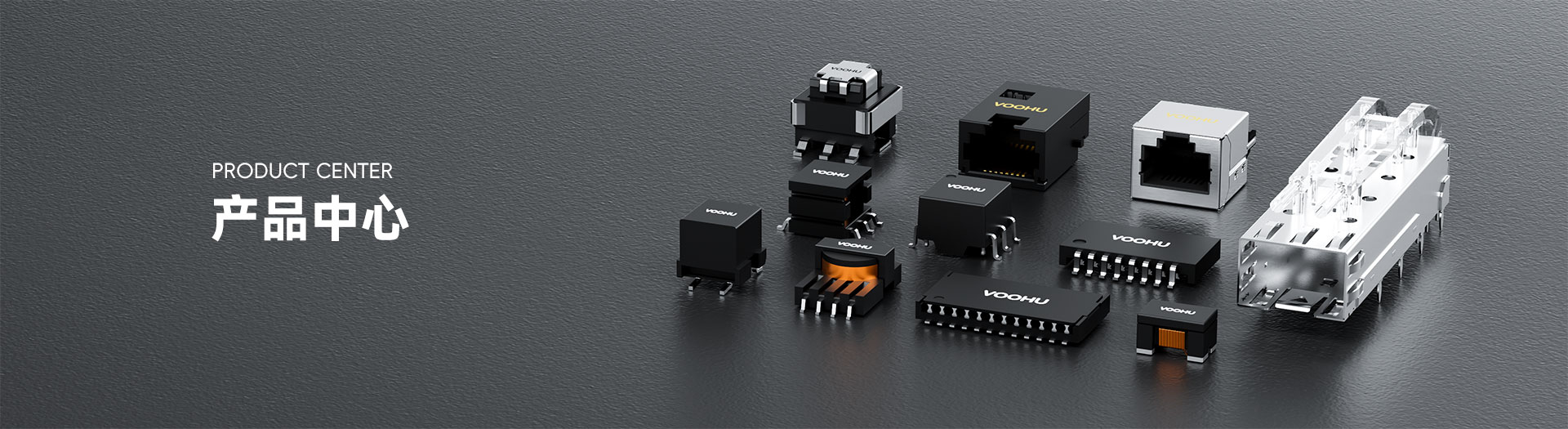
WHD20702G Dual Ports DIP 10/100Base-TX PIN20 non-PoE LAN Transformer


Request a Quote
Leave your details and we will send a tailored volume quote.
Our sales team will contact you within 1 business day.
Contact Sales
Reach our sales team for pricing and lead time.

Submitted
We have received your request. Our sales team will contact you within 1 business day.


For technical assistance, pleaseclick the button below to add customer service or visit the sample request pageto fill out the form. We will serve you as soon as possible.
Technical Support Email: fae.thorne@voohu.cn Phone: +86 400-1048-018
For more details, please visit theDownload Centerto get documents or click the button below to add customer service. We will serve you as soon as possible.


For purchases and small-volume orders, please contact our sales team. We support VAT general/special invoices with a convenient and efficient process.
For technical assistance or sample requests, pleaseclick the button belowto add customer service orvisit the sample request pageto fill out the form. We will serve you as soon as possible.
Customer Service Email: song.lei@voohu.cn Phone: +86 180 2130 1120
The two match on electrical ratings and hole pattern, so choose purely by which side the common-mode choke should land on: the WHD20702G puts it on the cable side, theWHD20701Gon the chip side.
The deciding factor is the element order in the PHY reference design and the EMC result on the finished unit, not a better or worse number — the parameter table shows no difference. Swapping after the board is fixed costs no footprint work but does need EMC re-measured.
Not at all. The WHD20702G is 2.00 mm pitch with an 18.00 mm span on a 21.20 × 10.00 mm body; the2.54 mm familyspans 22.86 mm on a 25.40 × 10.00 mm body.
All twenty hole positions differ and the body is 4.2 mm longer. Row spacing does happen to be 7.62 mm on both, but matching row spacing alone means nothing — the hole-to-hole interval differs, so every hole in the row is displaced. Where board length is tight the 2.00 mm family saves space; where an existing 0.1-inch-grid board is being reused, the 2.54 mm family is the one.
Indoor dual 100M port equipment where the component temperature stays between 0 °C and +70 °C and the PCB carries a 20-pin through-hole layout on 2.00 mm pitch with 7.62 mm row spacing.
The WHD20702G has no PoE capability, so both ports are powered locally; the body is 21.20 × 10.00 mm, 7.20 mm Max high, with 3.20 mm leads, wave-soldered. A board drilled to 10.16 mm row spacing cannot take this part — see the10/100 BASE-T rangefor that outline.