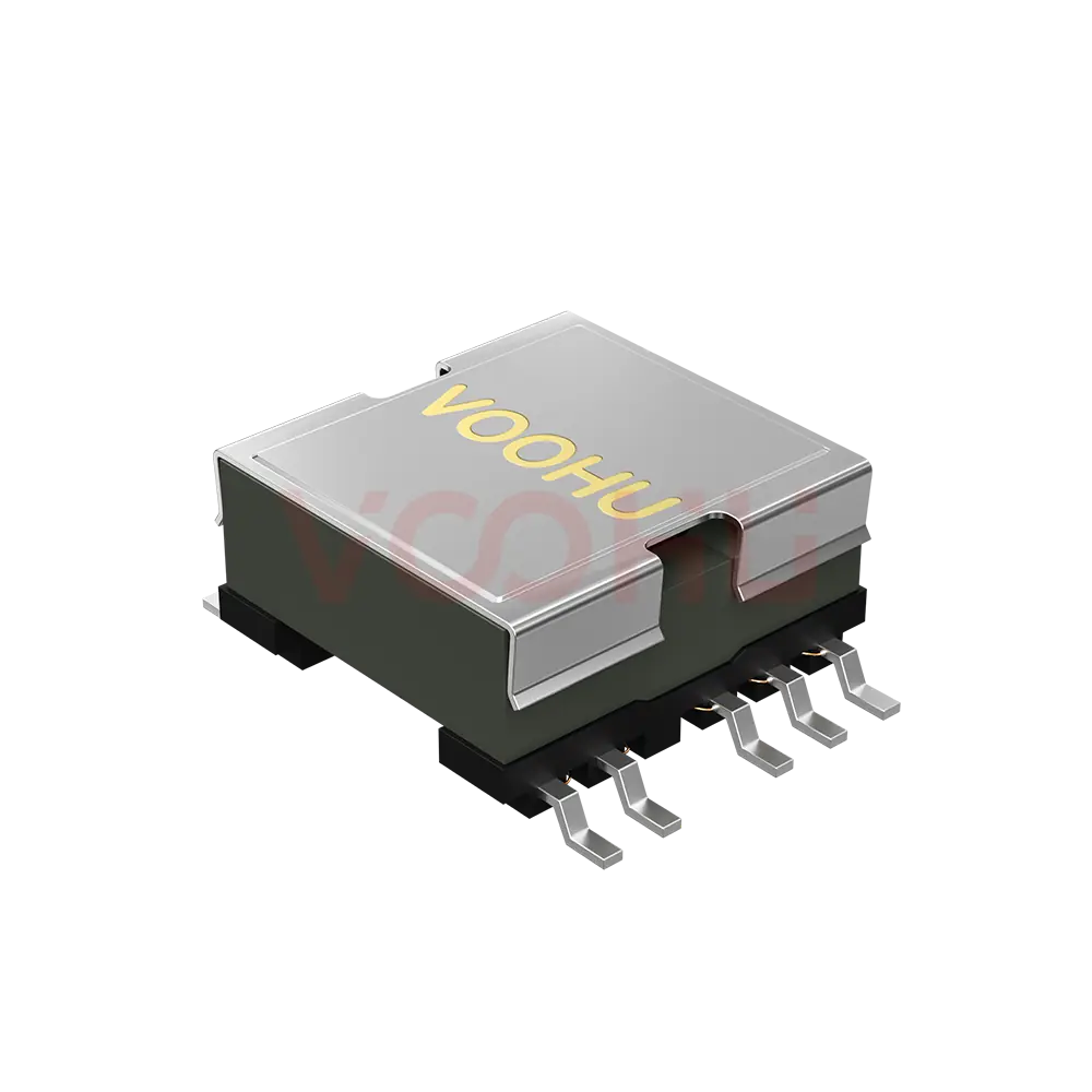
WHSM24P01P1 Single Port SMD 18G PIN24 4PPoE LAN Transformer


Request a Quote
Leave your details and we will send a tailored volume quote.
Our sales team will contact you within 1 business day.
Contact Sales
Reach our sales team for pricing and lead time.

Submitted
We have received your request. Our sales team will contact you within 1 business day.


For technical assistance, pleaseclick the button below to add customer service or visit the sample request pageto fill out the form. We will serve you as soon as possible.
Technical Support Email: fae.thorne@voohu.cn Phone: +86 400-1048-018
For more details, please visit theDownload Centerto get documents or click the button below to add customer service. We will serve you as soon as possible.


For purchases and small-volume orders, please contact our sales team. We support VAT general/special invoices with a convenient and efficient process.
For technical assistance or sample requests, pleaseclick the button belowto add customer service orvisit the sample request pageto fill out the form. We will serve you as soon as possible.
Customer Service Email: song.lei@voohu.cn Phone: +86 180 2130 1120
In two ways: the bands extend from 500 MHz to 800 MHz, and crosstalk and common-mode rejection are given as minimum limits rather than typical values.The WHSM24P01P1 specifies crosstalk as -40 dB min in the lowest band, tightening to -18 dB min at the top. Common-mode rejection is -15 dB min from 400 to 800 MHz.
A minimum can go straight into a worst-case budget, whereas the 10G parts in this range quote these two as typical values and can only be treated as design references. The datasheet also lists DCMR separately, again as minimums across three bands, so include it when calculating link margin.
The datasheet states PoE Support 60W for the WHSM24P01P1, with 720 mA of DC balance current per magnetic channel and 1440 mA across full channels.The 1440 mA figure is what the port carries with its two channels working together – not the rating of any single centre-tap path, and not 720 mA multiplied by the coil count.
Size four balanced copper paths against 720 mA each, calculating width from your actual copper thickness and permitted temperature rise.
When the link runs beyond the 500 MHz range a 10G part defines, or when the project has to sign off against limits rather than typical values.Those two points are the real dividing line between the WHSM24P01P1 and the 10G parts in this range: it is defined to 800 MHz where they stop at 500 MHz, and its crosstalk and common-mode rejection are minimums where theirs are typicals.
If the link is genuinely 10GBASE-T and the margin analysis accepts typical values, a 10G part is usually the better fit on cost and availability. This part operates from 0 °C to +85 °C. Other speed classes are listed in the10G BASE-T range.