




Initial inductance
Measured at low current before any roll-off. Ranges from about 100 to 500 nanohenries across the WHPBU series, which suits high frequency multiphase stages.
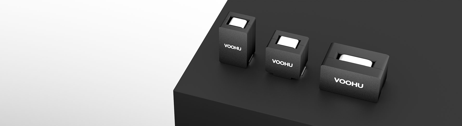
インダクター製品
These are single-winding power bead inductors for multiphase buck converters and point-of-load stages: nanohenry inductance, sub-milliohm DC resistance and saturation currents past a hundred amps. Select on the hot saturation figure and the heating current, not the room-temperature number.
型番検索・選定
この表では、海外サイトの現行製品データ、公開済みの選定項目、型番別の技術資料リンクを使用しています。
※画像列と型番列は固定されています。横にドラッグしてすべての仕様を確認できます
| 画像 | データシート | 比較 | ダウンロード |
カテゴリー
|
初期インダクタンス(nH)
|
許容差(±%)
|
DCR(mΩ)
|
1-飽和電流@25℃(A)(代表値)
|
2-飽和電流@100℃(A)(代表値)
|
温度上昇電流(A)(代表値)
|
サンプル |
|---|
| 画像 | 型番 | データシート | 比較 | ダウンロード | カテゴリー | 初期インダクタンス(nH) | 許容差(±%) | DCR(mΩ) | 1-飽和電流@25℃(A)(代表値) | 2-飽和電流@100℃(A)(代表値) | 温度上昇電流(A)(代表値) | サンプル |
|---|---|---|---|---|---|---|---|---|---|---|---|---|
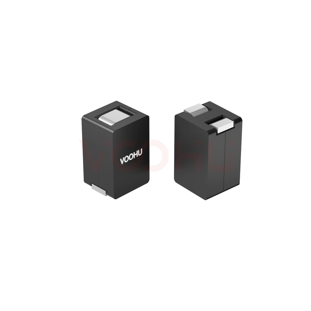 |
WHPBU-131308N-R50L0 | SPEC | WHPBU-131308N | 500 | 15 | 0.32 ± 9.4% | 28 | 23 | 45 |
|
||
|
|
WHPBU-131308N-R44L0 | SPEC | WHPBU-131308N | 440 | 15 | 0.32 ± 9.4% | 35 | 25 | 45 |
|
||
|
|
WHPBU-131308N-R32L0 | SPEC | WHPBU-131308N | 320 | 15 | 0.32 ± 9.4% | 50 | 35 | 45 |
|
||
|
|
WHPBU-131308N-R26L0 | SPEC | WHPBU-131308N | 260 | 15 | 0.32 ± 9.4% | 60 | 45 | 45 |
|
||
|
|
WHPBU-131308N-R21L0 | SPEC | WHPBU-131308N | 210 | 15 | 0.32 ± 9.4% | 70 | 55 | 45 |
|
||
|
|
WHPBU-131308N-R11K0 | SPEC | WHPBU-131308N | 110 | 10 | 0.32 ± 9.4% | 120 | 105 | 45 |
|
選択した条件を広げるか、現在の検索条件をクリアしてください。
By series
Series differ in body size, which sets DC resistance and how much current each phase carries.
選定方法
Phase count and ripple set the inductance; thermals and peak current set the series.
Work from input and output voltage, switching frequency, phase count and the ripple you can accept. More phases and higher frequency both reduce the inductance each phase needs.
Use the saturation figure at 100 degrees, not the 25 degree number. Your per-phase peak, including load transients, has to stay inside it.
Heating current caps the continuous RMS per phase. Multiply DC resistance by that current squared to see the copper loss the board has to shed.
Check body size, land pattern and phase-to-phase spacing, then measure ripple, current sharing and temperature rise on the real board.
Parameters
Two saturation figures and a heating current, each defined under different conditions.
Measured at low current before any roll-off. Ranges from about 100 to 500 nanohenries across the WHPBU series, which suits high frequency multiphase stages.
Stated as a percentage around the initial inductance. It feeds directly into your ripple calculation, so use the worst-case corner rather than the nominal value.
Sub-milliohm across the range, from about 0.18 to 0.47 milliohm depending on series. At high phase current even a tenth of a milliohm is measurable heat.
The room-temperature limit, useful for comparing parts but optimistic for design. A real converter runs hotter than its test bench.
The figure to design against. Saturation capability falls as the core heats, so this is what your peak phase current must stay below.
The continuous RMS current that produces the datasheet's stated temperature rise. It caps steady-state load, while saturation caps the peak.
比較
DC resistance and heating current separate the series more than inductance does.
選定表に戻る ↑| カテゴリー | 型番数 | 初期インダクタンス(nH) | 許容差(±%) | DCR(mΩ) | 1-飽和電流@25℃(A)(代表値) | 2-飽和電流@100℃(A)(代表値) | 温度上昇電流(A)(代表値) | 操作 |
|---|---|---|---|---|---|---|---|---|
| WHPBU-100705N | 7 | 72, 100, 120, 150, 200, 220, 300 | 15 | 0.325±7% | 19, 30, 33, 45, 65, 70, 80 | 12, 24, 25, 35, 50, 60, 70 | 31 | 絞り込み → |
| WHPBU-100710N | 8 | 100, 120, 150, 180, 220, 300, 330, 470 | 15, 20 | 0.18±10% | 20, 35, 43, 60, 75, 90, 117 | 15, 30, 33, 50, 65, 75, 80, 100 | 70 | 絞り込み → |
| WHPBU-131308N | 6 | 110, 210, 260, 320, 440, 500 | 10, 15 | 0.32 ± 9.4% | 28, 35, 50, 60, 70, 120 | 23, 25, 35, 45, 55, 105 | 45 | 絞り込み → |
| WHPBU-150705N | 3 | 100, 120, 150 | 15 | 0.47±7% | 72, 87, 105 | 60, 75, 80 | 53 | 絞り込み → |
用途別確認
Confirm phase count, per-phase current, switching frequency and the thermal environment.
Documents
Datasheets carry the saturation curves, heating current and recommended land pattern.
代表的な入手可能資料を表示しています。特定のSKUは検索して確認してください。
VOOHUが公開する製品情報は、エンジニアリングチームが確認しています。仕様、ダウンロード資料、技術サポート情報は型番ごとに紐付けられているため、サンプルや見積もりを依頼する前に確認できます。
カテゴリー概要
These parts are often mislabelled. Knowing what they are, and which of the three current figures to design against, prevents most of the errors.
型番が決まっている場合は、サンプルまたは見積もりを依頼。
A power bead inductor is a single winding of one or two turns over a ferrite core. It is not a coupled inductor and not a common mode choke, both of which have two windings that interact magnetically. The construction gives very low DC resistance and very high saturation current in a small body.
Saturation at 25 degrees is a comparison number. Saturation at 100 degrees is the one your peak phase current must stay under, because the core loses capability as it heats. Heating current is the continuous RMS that produces the rated temperature rise. Size the peak on the hot figure, the steady state on heating current.
With phase currents in the tens of amps, loss rises with the square of current. A part at 0.18 milliohm and one at 0.47 milliohm differ by more than a factor of two in copper loss. On a dense multiphase board that shows up directly as board temperature, so read DCR early rather than last.
よくあるご質問
Answers cover what a power bead is, which current rating to design against and how to compare.
It is a single-winding power inductor, usually one or two turns over a ferrite core, designed for very low DC resistance and very high saturation current in a small body. It is the standard choice for multiphase buck converters powering processors, FPGAs and ASICs, where each phase carries tens of amps at low inductance.
No. A coupled inductor has two or more windings that interact magnetically and is used to shape ripple across phases. A power bead is a single winding with no magnetic coupling between phases. The two are not interchangeable, and the datasheets describe different things, so do not substitute one for the other.
The figure at 100 degrees. Saturation capability falls as the core heats, and a working converter runs well above room temperature. The 25 degree number is useful for comparing parts on equal terms, but sizing a design against it leaves no margin once the board is hot.
Heating current is the continuous RMS current that produces the temperature rise stated in the datasheet. It caps the steady-state load each phase can carry. Saturation current caps the instantaneous peak. Both have to be satisfied: heating current for the average, hot saturation for the transient.
Because loss rises with the square of current, and phase currents here are tens of amps. Across the WHPBU range DC resistance runs from about 0.18 to 0.47 milliohm, which is more than a factor of two in copper loss at the same current. On a dense board that shows up directly as temperature.
Work from input and output voltage, switching frequency, phase count and the ripple current you can accept. More phases and higher switching frequency both reduce the inductance each phase needs, which is why these parts are specified in nanohenries rather than microhenries.
It is not advisable. Phases should be as identical as possible, because differences in inductance and DC resistance cause unequal current sharing, and the phase carrying the most current runs hottest and saturates first. Use the same part across all phases and verify the sharing by measurement.
With a complete part number, send the part number, quantity, delivery region and the date you need it. If you are still selecting, send the total output current, phase count, per-phase RMS and peak current, switching frequency and ambient temperature.
エンジニアサポート
候補型番と、確認が必要な条件をお送りください。候補が明確になった後にサンプル支援を追加でき、商取引に関するご質問も同じ技術相談の中でご相談いただけます。
資料のリビジョンも記載してください
温度、絶縁電圧、PoE電流の条件
ピン数、ピッチ、ピン列間隔
サンプルと評価の優先度確認に使用します
候補と相違点の比較が必要な時期
エンジニア確認により候補型番を選び、相違点をご説明します。
選定表またはエンジニア確認で選んだ型番
試作/パイロット生産/量産
サンプルと量産の時期を分けて記載してください
適合資料、材料宣言、第三者機関レポートなど
サンプル数量、リードタイム、費用は、プロジェクト段階と型番によって異なります。営業担当者より営業日にご回答します。




