Grundursache
Die Ursache des Problems liegt in der Behandlung des Transformators als „Pass-Through“-Komponente – vorausgesetzt, dass ein Signal, das an Pin 1 geht, auch an Pin 4 kommen sollte.
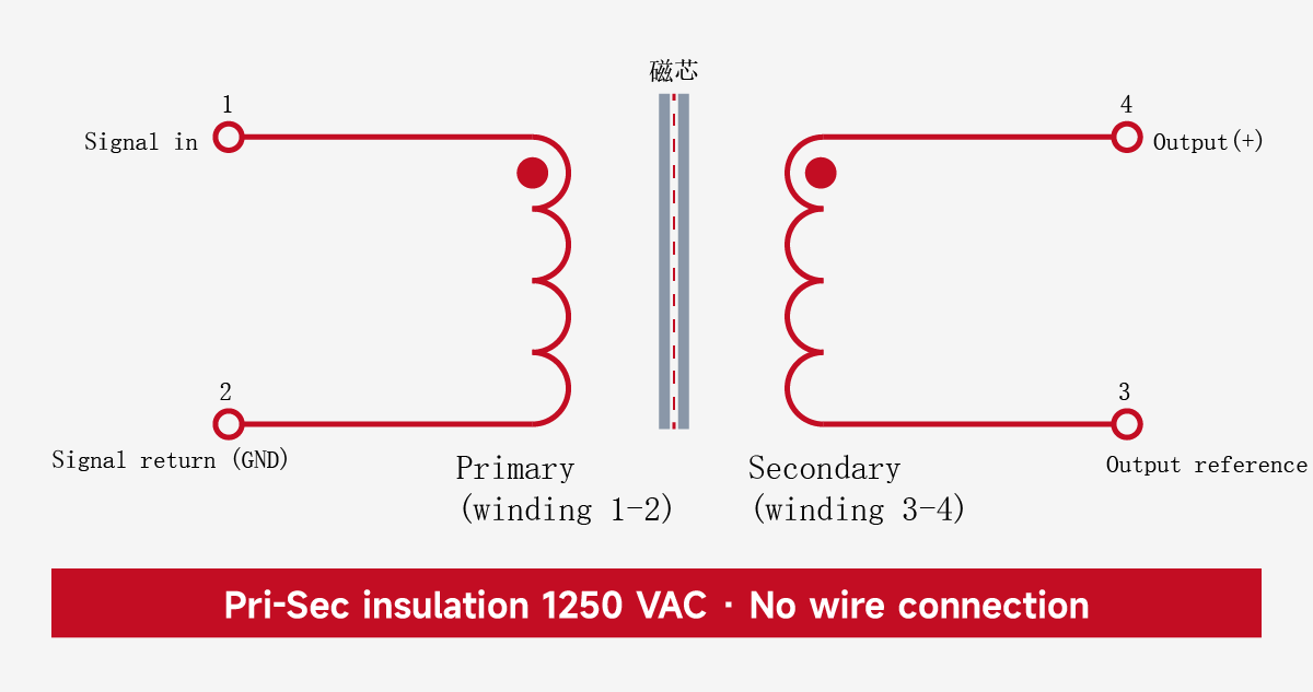
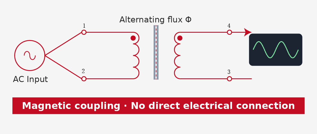
Aber ein Transformator funktioniert so nicht. Wenn ein Wechselstromsignal an die Primärwicklung (1-2) angelegt wird, erzeugt es einen magnetischen Wechselfluss im Kern. Dieser Fluss induziert ein Signal in der Sekundärseite (3-4) und regeneriert das Signal auf dieser Seite.
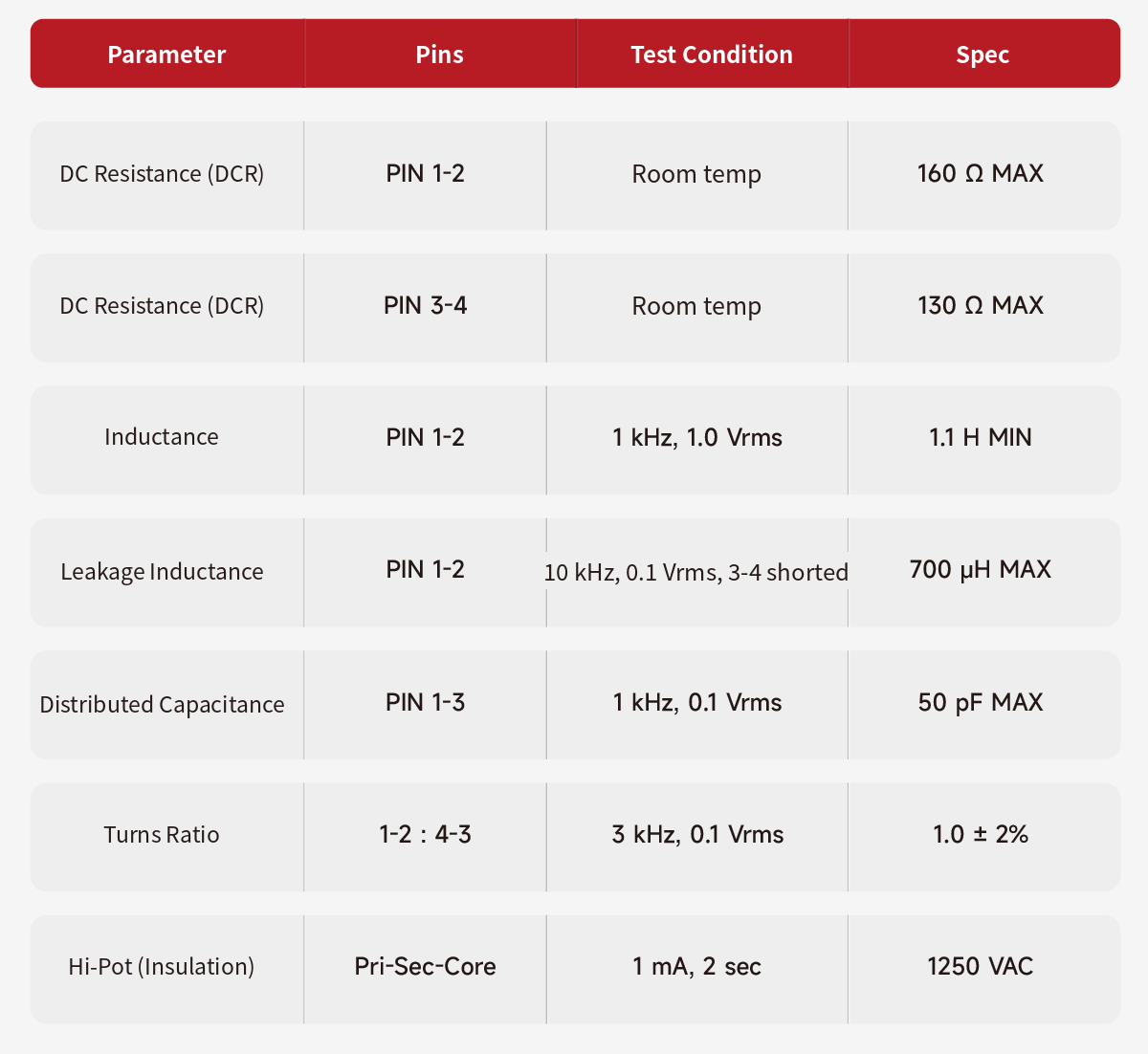
Die Energieübertragung beruht vollständig auf magnetischer Kopplung; Die Primär- und Sekundärwicklung sind gleichstromisoliert und isoliert (mit Ausnahme der minimalen parasitären Kapazität – siehe Spezifikation der Wicklungskapazität von 1-3 ≤50 pF, die bei Gleichstrom offen bleibt; die Hochfrequenz-Gleichtaktunterdrückung wird durch diese Kapazität begrenzt).
Daraus ergeben sich zwei Schlussfolgerungen:
Erstens „läuft“ das Signal nicht von Pin 1 zu Pin 4. Die Tatsache, dass die Pins 1 und 4 nicht direkt leitend sind, ist konstruktionsbedingt – das Blockieren von Gleichstrom, das Unterbrechen von Masseschleifen, die Unterdrückung von Gleichtaktstörungen und die Bereitstellung einer elektrischen Isolierung sind genau der Wert eines Trenntransformators.
Zweitens haben das Primär- und das Sekundärsystem keine Gemeinsamkeiten. Die Sekundärseite (3-4) ist relativ zur Primärseite (1-2) schwebend; es gibt keinen festen Potentialbezug zwischen den beiden Seiten.
Warum die Single-Ended-Messung an Pin 4 kein Signal erkennt
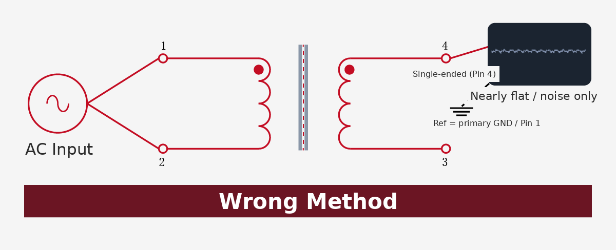
Die Messmethode des Kunden bestand darin, Pin 4 relativ zur Masse oder relativ zu Pin 1 im Single-Ended-Modus zu messen. Allerdings ist die Spannung an Pin 4 nur relativ zum anderen Ende derselben Wicklung (Pin 3) aussagekräftig.
Die Sekundärwicklung ist erdfrei und hat keinen Bezug zur Primärmasse. Die Messung von Pin 4 gegen die Primärmasse oder Pin 1 erfasst nur Gleichtaktrauschen oder eine Streuspannung nahe Null – natürlich wird keine nützliche Wellenform beobachtet.
Das Gerät ist also nicht fehlerhaft; Der Bezugspunkt wurde falsch gewählt.
Korrekte Prüf- und Verdrahtungsmethoden
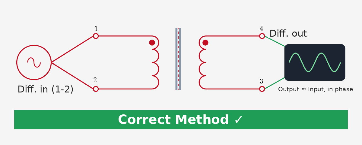
Um die Signalübertragung durch den WHTT4005 zu überprüfen, befolgen Sie ein Prinzip: Differenzeingang, Differenzausgang.
Eingangsseite:
Erregen Sie die Wicklung 1-2 – verbinden Sie das Signal mit Pin 1 und die Rückleitung der Signalquelle mit Pin 2, sodass eine vollständige Schleife entsteht. Schließen Sie nicht nur Pin 1 an.
Ausgangsseite:
Führen Sie eine Differenzmessung an der 4-3-Wicklung durch – messen Sie die Spannung von Pin 4 relativ zu Pin 3. Messen Sie nicht Single-Ended zur Erde oder zu Pin 1.
Erdungsbezogenes Oszilloskop:
Wenn Sie nur über ein herkömmliches massebezogenes Oszilloskop verfügen, verbinden Sie zuerst den Sekundärstift 3 als Referenz mit der Messmasse und dann den Sondenstift 4.
Erwartetes Ergebnis:
Bei einem 1:1-Transformator entspricht die Ausgangsamplitude ungefähr der Eingangsamplitude (abzüglich Einfügedämpfung) und Pin 4 ist in Phase mit Pin 1.
Die Bedeutung der Impedanzanpassung und -isolierung von 600:600 Ω
Der WHTT4005 hat eine Nennimpedanz von 600:600 Ω, was bedeutet, dass er für die Impedanzanpassung von 600 Ω in Audioleitungsanwendungen vorgesehen ist – die klassische charakteristische Impedanz für Telefon- und professionelle Audioschaltungen. Das Windungsverhältnis von 1:1 bedeutet, dass sich die Signalamplitude nicht wesentlich ändert. Es erfüllt nur zwei Funktionen: Isolierung und Impedanzanpassung.
Das Hinzufügen eines solchen Geräts – eines, das für Isolierung ohne Verstärkung sorgt – zu einer Signalkette dient vier Hauptzwecken:
-
Blockieren Sie DC- und Erdpotentialunterschiede: Verhindern Sie Erdschleifen, die durch unterschiedliche Erdpotentiale zwischen zwei Geräten verursacht werden, und eliminieren Sie das daraus resultierende Wechselstrombrummen.
-
Gleichtaktstörungen unterdrücken: Lassen Sie das Differenzsignal (Nutzsignal) durch und blockieren Sie gleichzeitig Gleichtaktstörungen an beiden Enden.
-
Sorgen Sie für elektrische Isolierung: Die Primär-zu-Sekundär-Spannungsfestigkeit (Hi-Pot) von 1250 VAC blockiert Gleich- und Erdpotenzialunterschiede und verhindert so, dass Fehler oder abnormale Spannungen direkt von einer Seite zur anderen übertragen werden, und sorgt so für eine funktionale Isolierung für nachgeschaltete Schaltkreise. (Hinweis: Bei diesem Wert handelt es sich um eine werkseitige Hi-Pot-Testbedingung und nicht um eine Sicherheitsisolationsbewertung für den Dauerbetrieb. Verwenden Sie zum Schutz der Personen Isolationsvorrichtungen mit Sicherheitszertifizierung, ausreichenden Kriech-/Luftstrecken und definierten Arbeitsspannungsnennwerten.)
-
Schaltkreistopologiekonvertierung aktivieren: Konvertieren zwischen symmetrischen (differentiellen) und unsymmetrischen (single-ended) Schaltkreisen.
Auswahl- und Lösungsunterstützung
Die Isolierung und Filterung in Audio- und industriellen Signalketten kann oft nicht durch eine einzelne Komponente gelöst werden. VOOHU bietet eine komplette Auswahl an unterstützenden Komponenten – von Audio-Trenntransformatoren, LAN-Transformatoren und Gleichtaktdrosseln bis hin zu TVS/ESD/GDT-Schutzgeräten:
-
WHTT4005 und andere Audio-Trenntransformatorserien: Deckt gängige Impedanzen wie 600:600 Ω ab und bietet 1:1-Isolierung und Impedanzanpassung für professionelle Audio-, Rundfunkkommunikations- und Industrieinstrumentierung.
-
Gleichtaktdrosseln und Schutzgeräte: Arbeiten Sie mit Trenntransformatoren zusammen, um die Rauschunterdrückung und den Überspannungsschutz zu verbessern.
-
Technischer Support: Referenzschaltungen, Auswahlempfehlungen und Kriterien für die Eingangsprüfung sind verfügbar, mit Anpassung an spezifische Anwendungsanforderungen.
Häufig gestellte Fragen (FAQ)
F: Ich habe ein Signal an Pin 1 angelegt, kann aber an Pin 4 keinen Ausgang messen. Ist der Transformator defekt?
A: In den meisten Fällen nein. Die Pins 1 und 4 des WHTT4005 gehören zu zwei voneinander isolierten Wicklungen ohne direkte Drahtverbindung. Die Signalübertragung erfolgt über magnetische Kopplung von der Primärseite (1-2) zur Sekundärseite (3-4); Es soll nicht von Pin 1 zu Pin 4 „durchgehen“. Wenn Sie Pin 4 Single-Ended gegen Masse oder Pin 1 messen, werden Sie nur Gleichtaktrauschen oder eine Streuspannung nahe Null ablesen – daher „kein Signal“. Hierbei handelt es sich um einen Referenzpunktfehler, nicht um ein defektes Gerät.
F: Was ist die richtige Testmethode?
A: Befolgen Sie das Prinzip „Differenzeingang, Differenzausgang“: Legen Sie am Eingang eine Erregung über 1-2 an (Signal an Pin 1, Rückkehr an Pin 2), um eine vollständige Schleife zu bilden. Messen Sie am Ausgang die Differenzspannung von Pin 4 relativ zu Pin 3. Messen Sie Single-Ended nicht gegen Masse oder Pin 1. Wenn Sie nur ein Oszilloskop mit Massebezug haben, verbinden Sie zuerst Sekundärpin 3 als Referenz mit der Messmasse und messen Sie dann Pin 4. Bei einem 1:1-Transformator entspricht die Ausgangsamplitude ungefähr der des Eingangs und Pin 4 ist in Phase mit Pin 1.
F: Wie kann ich das Gerät ohne Signalquelle schnell mit einem Multimeter überprüfen?
A: Verwenden Sie den Widerstandsbereich: Pins 1–2 sollten kontinuierlich sein (≤ 160 Ω), Pins 3–4 sollten kontinuierlich sein (≤ 130 Ω) und jede Primär-zu-Sekundär-Pin-Kombination (1–3, 1–4, 2–3, 2–4) sollte einen offenen Stromkreis (unendlich) anzeigen. Wenn beide Wicklungen durchgehend sind und kein Durchgang zwischen Primär- und Sekundärwicklung besteht, ist das Gerät grundsätzlich in Ordnung. Wenn zwischen Primär- und Sekundärseite Durchgang besteht, ist die Isolierung ausgefallen.
Suzhou VOOHU Electronics Technology Co., Ltd. (VOOHU) ist seit vielen Jahren intensiv im Bereich der Kommunikationselektronik tätig. Für verschiedene Anwendungsszenarien bieten wir Komponentenauswahl und technischen Support für Audio-Trenntransformatoren und zugehörige Geräte.