




Port notation
A figure such as 5+1 means five external ports plus one host uplink. A single figure such as 5 or 8 means external ports only, with no separate uplink.
Ethernet-Schnittstellenchips
JL6108 provides eight external gigabit ports with no host uplink, in an LQFP128 package measuring 20 by 14 millimetres. Eight gigabit ports concentrate significant power and board area, so plan the thermal design and panel layout early.
Artikelsuche und Produktauswahl
Die Tabelle verwendet die aktuellen Produktdatensätze der englischsprachigen Website, veröffentlichte Auswahlfelder und artikelspezifische Links zu technischen Dateien.
* Spalten „Bild“ und „Artikelnummer“ fixiert · horizontal ziehen, um alle Spezifikationen anzuzeigen
| Bild | Datenblatt | Vergleichen | Downloads |
Serie
|
Datenrate
|
Ports
|
Schnittstellenmodus
|
MAC-Schnittstellenspannung
|
Externe Versorgungsspannung
|
Kupfer-Port
|
Optischer Port
|
Temperatur
|
Gehäuse
|
Baugröße
|
Muster |
|---|
| Bild | Artikelnummer | Datenblatt | Vergleichen | Downloads | Serie | Datenrate | Ports | Schnittstellenmodus | MAC-Schnittstellenspannung | Externe Versorgungsspannung | Kupfer-Port | Optischer Port | Temperatur | Gehäuse | Baugröße | Muster |
|---|---|---|---|---|---|---|---|---|---|---|---|---|---|---|---|---|
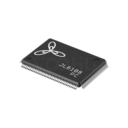 |
JL6108-PC | SPEC | JL6108-Serie | 1G | 8 | NA | NA | 1.1V | 10 Base-T | NA | 0~70℃ | LQFP128 | 20*14 mm |
|
Erweitern Sie die ausgewählten Filter oder löschen Sie die aktuelle Suche.
By port topology
Port notation such as 5+1 means five external ports plus one host uplink.
So wählen Sie aus
Topology first, then speed, then the supply rails, then package and thermals.
Count the external ports you need, then decide whether the host has to send and receive traffic. If it does, you need a device with an uplink port.
The range covers 100M and gigabit. There are no 2.5G or faster devices here, so if the design needs those speeds, say so at enquiry.
Most devices need a low voltage core rail alongside the main supply. Confirm the rails and their sequencing before the power tree is fixed.
Packages run from QFN48 at 6 by 6 up to TQFP176 at 20 by 20 millimetres. Higher port counts concentrate more heat in one device.
Parameters
Port notation and the supply requirement are the two figures most often misread.
A figure such as 5+1 means five external ports plus one host uplink. A single figure such as 5 or 8 means external ports only, with no separate uplink.
100M on the JL51xx series, gigabit on the JL61xx series. Every device also supports 10Base-T on copper for legacy links.
MII on most devices with an uplink, RMII on the JL5104. Devices listed as NA have no dedicated host interface at all.
Typically a 3.3 volt main supply with a 1.1 volt core rail, or 1.1 volt alone on some gigabit parts. Missing a rail prevents the device starting.
1000Base-X appears on the JL6110 and on the S variants of the JL6107. Other devices in the range are copper only.
NC and PC suffixes cover 0 to 70 degrees; NI and PI cover minus 40 to 85. Not every series offers both grades.
Vergleichen
Port count and uplink presence separate the series more than speed does.
Zur Produktauswahl zurückkehren ↑| Serie | Artikelnummern | Datenrate | Ports | Schnittstellenmodus | MAC-Schnittstellenspannung | Externe Versorgungsspannung | Kupfer-Port | Optischer Port | Temperatur | Gehäuse | Baugröße | Aktion |
|---|---|---|---|---|---|---|---|---|---|---|---|---|
| JL5104-Serie | 2 | 100M | 3+1 | RMII | 3.3V | 3.3V(1.1V)¹ | 10 Base-T | NA | 0~70℃, -40~85℃ | QFN48 | 6*6 mm | Filtern → |
| JL5105-Serie | 2 | 100M | 5 | NA | NA | 3.3V(1.1V)¹ | 10 Base-T | NA | 0~70℃, -40~85℃ | QFN48 | 6*6 mm | Filtern → |
| JL5106-Serie | 2 | 100M | 5+1 | MII | 3.3V | 3.3V(1.1V)¹ | 10 Base-T | NA | 0~70℃, -40~85℃ | QFN64 | 9*9 mm | Filtern → |
| JL5108-Serie | 2 | 100M | 8 | NA | NA | 3.3V(1.1V)¹ | 10 Base-T | NA | 0~70℃, -40~85℃ | QFN64 | 9*9 mm | Filtern → |
| JL5109-Serie | 1 | 100M | 8+1 | MII | 3.3V | 3.3V(1.1V)¹ | 10 Base-T | NA | 0~70℃ | QFN88 | 10*10 mm | Filtern → |
| JL5110-Serie | 1 | 100M | 8+2 | MII | 3.3V | 3.3V(1.1V)¹ | 10 Base-T | NA | 0~70℃ | QFN88 | 10*10 mm | Filtern → |
| JL6105-Serie | 1 | 1G | 5 | NA | NA | 1.1V | 10 Base-T | NA | 0~70℃ | QFN88 | 10*10 mm | Filtern → |
| JL6107-Serie | 6 | 1G | 5+2 | MII | 1.8V | 1.1V, 3.3V(1.1V)¹ | 10 Base-T | NA, 1000 Base-X | 0~70℃, -40~85℃ | LQFP128 | 14*14 mm | Filtern → |
| JL6108-Serie | 1 | 1G | 8 | NA | NA | 1.1V | 10 Base-T | NA | 0~70℃ | LQFP128 | 20*14 mm | Filtern → |
| JL6110-Serie | 2 | 1G | 8+2 | MII | 3.3V | 1.1V | 10 Base-T | 1000 Base-X | 0~70℃, -40~85℃ | TQFP176 | 20*20 mm | Filtern → |
Anwendungsprüfung
Confirm the port topology, whether the host must manage traffic, and the environment.
Documents
Datasheets carry the supply sequencing, pinout and reference schematic per device.
Es werden repräsentative verfügbare Dateisätze angezeigt. Suchen Sie nach einer bestimmten Artikelnummer.
Die veröffentlichten Produktinhalte von VOOHU werden vom technischen Team geprüft. Spezifikationen, Downloads und Informationen zum technischen Support sind bestimmten Artikelnummern zugeordnet, sodass Sie sie vor einer Muster- oder Angebotsanfrage prüfen können.
Kategorieübersicht
Almost every selection question on switch ICs comes down to the port notation and whether the host controller needs to be on the network.
Neues Design besprechen
FAE für eine Ersatztypenprüfung kontaktieren.
Sie haben bereits eine Artikelnummer? Muster oder Angebot anfragen.
The first figure is external ports facing the outside world. The figure after the plus is a host uplink, a dedicated interface for the controller on the same board. A device listed as 5 has five external ports and no uplink, so the host cannot send or receive traffic through it. That distinction eliminates half the range.
If the product only has to move traffic between its own front panel ports, a device with external ports only is simpler and cheaper to lay out. If the host has to participate, for management, for remote access or because it originates data, you need an uplink and the host must provide the matching MII or RMII interface.
Most devices here need more than one rail: commonly 3.3 volts for the main supply and around 1.1 volts for the core, and some gigabit parts run the core alone. Missing a rail, or sequencing them wrongly, prevents the device starting. Confirm the rails and sequence before the power tree is committed.
FAQ
Answers cover port notation, uplinks, supply rails and fibre support.
Products with a dense front panel where the host controller plays no part in forwarding. It keeps the design free of uplink routing. If the product needs management, remote access or host traffic, compare the JL6110 which adds two uplinks and fibre support.
Considerably more than the 20 by 14 millimetre package. Each of the eight gigabit ports needs magnetics and a controlled impedance differential pair to its connector. Plan the port area, the magnetics placement and the panel arrangement before you place the device.
Eight gigabit ports in one package concentrate significant power. Follow the datasheet thermal pad requirements, provide generous copper and via stitching, and plan airflow in the enclosure. Measure the case temperature at full load at the highest rated ambient rather than relying on the rating alone.
Both provide eight external gigabit ports. JL6108 has no uplink and comes in LQFP128 at 20 by 14 millimetres. JL6110 adds two uplinks and 1000Base-X fibre support in a larger TQFP176 at 20 by 20. Decide on uplinks and fibre first.
With a complete part number, send the part number, quantity, delivery region and the date you need it. If you are still selecting, send the external port count and confirm whether the host needs to be on the network.
Technischer Support
Senden Sie die Artikelnummer des Kandidaten und die zu prüfende Bedingung. Muster können nach Abschluss der Auswahl angefragt werden; kaufmännische Fragen lassen sich im selben technischen Austausch klären.
Dokumentrevision angeben
Temperatur, Isolationsspannung und Bezugsgrundlage für den PoE-Strom
Pinzahl, Rastermaß und Abstand zwischen den Pinreihen
Zur Priorisierung von Mustern und Evaluierung
Zeitpunkt, zu dem Sie Kandidaten und einen Vergleich der Unterschiede benötigen
Die technische Prüfung ermittelt geeignete Kandidaten und erläutert die Unterschiede.
Aus der Produktauswahl oder technischen Prüfung
Prototyp / Pilotserie / Serienfertigung
Zeitplan für Muster und Serie getrennt angeben
Konformitätsnachweise, Materialdeklarationen oder Berichte Dritter
Mustermenge, Lieferzeit und Kosten hängen von der Projektphase und der Artikelnummer ab. Der Vertrieb antwortet an Werktagen.




