




Common mode impedance
What the choke presents to common mode noise, quoted at a stated frequency. Compare candidates at the same frequency or the numbers do not correspond.
Induktivitätsprodukte
WHLC2012A is another option in the 2012 size band, for differential interfaces where board area is the binding constraint. Compare the impedance curve against your failing band, then confirm the link still meets its eye and return loss targets.
Artikelsuche und Produktauswahl
Die Tabelle verwendet die aktuellen Produktdatensätze der englischsprachigen Website, veröffentlichte Auswahlfelder und artikelspezifische Links zu technischen Dateien.
* Spalten „Bild“ und „Artikelnummer“ fixiert · horizontal ziehen, um alle Spezifikationen anzuzeigen
| Bild | Datenblatt | Vergleichen | Downloads |
Baugröße
|
Gleichtaktimpedanz (10 MHz), min. Ω
|
Gleichtaktimpedanz (Ω typ.)
|
Induktivität (µH) +50/−30 %
|
RDC (Ω), max.
|
Streuinduktivität (nH), typ.
|
Isolationswiderstand (MΩ), min.
|
Nennstrom, max.
|
Nennspannung (V), max.
|
Muster |
|---|
| Bild | Artikelnummer | Datenblatt | Vergleichen | Downloads | Baugröße | Gleichtaktimpedanz (10 MHz), min. Ω | Gleichtaktimpedanz (Ω typ.) | Induktivität (µH) +50/−30 % | RDC (Ω), max. | Streuinduktivität (nH), typ. | Isolationswiderstand (MΩ), min. | Nennstrom, max. | Nennspannung (V), max. | Muster |
|---|---|---|---|---|---|---|---|---|---|---|---|---|---|---|
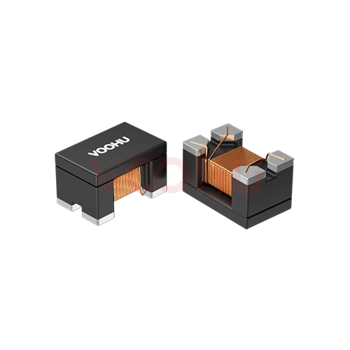 |
WHLC-2012A-121T1 | SPEC | 2012 | - | 120 | - | 0.3 | - | 10 | 400mA | 125 |
|
||
|
|
WHLC-2012A-381T0 | SPEC | 2012 | - | 380 | - | 0.45 | - | 10 | 300mA | 50 |
|
||
|
|
WHLC-2012A-900T0 | SPEC | 2012 | - | 90 | - | 0.35 | - | 10 | 300mA | 50 |
|
||
|
|
WHLC-2012A-181T0 | SPEC | 2012 | - | 180 | - | 0.35 | - | 10 | 300mA | 50 |
|
||
|
|
WHLC-2012A-261T0 | SPEC | 2012 | - | 260 | - | 0.4 | - | 10 | 300mA | 50 |
|
||
|
|
WHLC-2012A-361T1 | SPEC | 2012 | - | 360 | - | 0.45 | - | 10 | 300mA | 50 |
|
||
|
|
WHLC-2012A-801T0 | SPEC | 2012 | - | 800 | - | 0.88 | - | 10 | 300mA | 50 |
|
||
|
|
WHLC-2012A-102T0 | SPEC | 2012 | - | 1000 | - | 1.3 | - | 10 | 300mA | 50 |
|
||
|
|
WHLC-2012A-122T0 | SPEC | 2012 | - | 1200 | - | 1.5 | - | 10 | 300mA | 50 |
|
||
|
|
WHLC-2012A-750C | SPEC | 2012 | - | 75 | - | 0.55 | - | 10 | 280mA | 50 |
|
||
|
|
WHAC-2012A-801T0 | SPEC | 2012 | - | 800 | - | 0.88 | - | 10 | 300mA | 50 |
|
||
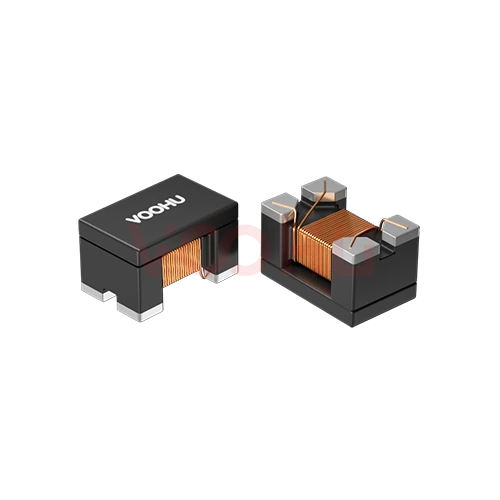 |
WHAC-2012A-900T0 | SPEC | 2012 | - | 90 | - | 0.35 | - | 10 | 300mA | 50 |
|
||
|
|
WHLC-2012A-121T0 | SPEC | 2012 | - | 120 | - | 0.3 | - | 10 | 400mA | 50 |
|
Erweitern Sie die ausgewählten Filter oder löschen Sie die aktuelle Suche.
By interface
The interface sets the data rate and therefore what the choke is allowed to do to the signal.
So wählen Sie aus
Interface first, then the failing band, then signal integrity, then the footprint.
USB, CAN bus, Ethernet and HDMI each set a data rate and a signalling scheme. That determines how much the choke is allowed to affect the signal.
Read the frequency range where the radiated or conducted scan exceeds the limit, then look for a part whose impedance is high across that range.
Check the impedance peak does not sit near your signal's fundamental, and that DC resistance does not add unacceptable loss on the pair.
Measure the eye diagram and return loss on your own board. Datasheet curves are taken in a reference fixture, not in your layout.
Parameters
Impedance is quoted at a frequency; so is everything else that matters here.
What the choke presents to common mode noise, quoted at a stated frequency. Compare candidates at the same frequency or the numbers do not correspond.
Matters when the pair also carries bias or power, as on some bus and PoE-adjacent designs. On a pure signal pair it is rarely the binding constraint.
Adds loss in the signal path and causes a voltage drop where the pair carries current. Read the maximum figure rather than a typical value.
How much of the wanted signal the part removes. Low values matter more as the data rate rises; verify by measurement rather than by datasheet alone.
Sets the board area and the spacing available between the differential traces. Smaller packages ease layout but usually offer lower impedance.
Asymmetry between the two windings turns common mode into differential noise. It is the reason a choke can make an eye diagram worse rather than better.
Vergleichen
Package size and impedance level separate the families; the interface decides which fits.
Zur Produktauswahl zurückkehren ↑| Baugröße | Artikelnummern | Gleichtaktimpedanz (10 MHz), min. Ω | Gleichtaktimpedanz (Ω typ.) | Induktivität (µH) +50/−30 % | RDC (Ω), max. | Streuinduktivität (nH), typ. | Isolationswiderstand (MΩ), min. | Nennstrom, max. | Nennspannung (V), max. | Aktion |
|---|---|---|---|---|---|---|---|---|---|---|
| 2012 | 13 | - | 120, 1200, 1000, 800, 380, 360, 260, 180, 90, 75 | - | 0.3, 0.35, 0.4, 0.45, 0.55, 0.88, 1.3, 1.5 | - | 10 | 280mA, 300mA, 400mA | 50, 125 | Filtern → |
| 3225 | 6 | 300, 500, 1000, 2200, - | 550, 1100, 2600, 5100, - | 11, 22, 51, 80, 100, 200 | 0.8, 1, 1.6, 2.5, 4, 4.9 | 50, 70, 130, 180, - | 10 | 70mA, 150mA, 200mA, 250mA, 300mA | 80 | Filtern → |
| 4532 | 21 | 300, 500, 1000, 2000, - | 600, 1200, 2800, 5800, 90±25%, 420±25%, 600±25%, 800±25%, 1000±25%, 1400±25%, 1400 | 11, 22, 51, 100, - | 0.25, 1.2, 1.4, 1.8, 2.5, 39, 60, 82, 89, 113, 148 | 50, 80, 150, 200, - | 10 | 150mA, 200mA, 250mA, 700mA, 1.0A, 1.5A, 1.8A, 2.0A, 2.2A, 3.0A | 50 | Filtern → |
Anwendungsprüfung
Confirm the interface, the data rate and whether the pair also carries bias current.
Documents
Datasheets carry the impedance curve, DC resistance and recommended land pattern.
Es werden repräsentative verfügbare Dateisätze angezeigt. Suchen Sie nach einer bestimmten Artikelnummer.
Die veröffentlichten Produktinhalte von VOOHU werden vom technischen Team geprüft. Spezifikationen, Downloads und Informationen zum technischen Support sind bestimmten Artikelnummern zugeordnet, sodass Sie sie vor einer Muster- oder Angebotsanfrage prüfen können.
Kategorieübersicht
On a power line the choke only has to pass current. On a signal pair it has to pass a waveform intact, which makes the selection harder.
Neues Design besprechen
FAE für eine Ersatztypenprüfung kontaktieren.
Sie haben bereits eine Artikelnummer? Muster oder Angebot anfragen.
A choke that works on a CAN bus can wreck a USB link, because the data rates differ by orders of magnitude. The interface sets how much insertion loss and how much impedance in the signal path the link can tolerate. Decide the interface and its rate before you start comparing impedance figures.
You want high common mode impedance across the band that fails your scan, and low impact at your signal's own frequencies. If the peak sits near the fundamental, the choke will attenuate the wanted signal as well as the noise. Read the curve, locate your two frequencies on it, and check they are far apart.
Real parts are never perfectly symmetric. Any imbalance between the two windings converts common mode noise into differential noise, which lands directly on the signal. This is why a choke sometimes makes an eye diagram worse. It cannot be predicted from the datasheet, so measure the eye and return loss on your own board.
FAQ
Answers cover interface fit, eye diagram impact and how to compare candidates.
Read each part's common mode impedance at the frequency your scan fails, compare maximum DC resistance, then check the recommended land pattern and the symmetry of the differential routing through the part. Finally verify on the target board, because layout changes the measured outcome.
Compact parts suit differential interfaces where trace spacing is constrained. Whether a given part fits a specific interface depends on its impedance curve and insertion loss, so send the interface and data rate and our engineers will confirm which candidates are appropriate.
No. Prefixes identify naming families, not performance tiers. Reading a ranking into the letters is a common mistake. Compare the actual impedance at the frequency you care about, along with DC resistance and the datasheet's stated test conditions.
Re-run the emission scan to confirm the failing band is now within limit, and measure the eye diagram and return loss to confirm the signal has not degraded. Both checks matter, because a choke that fixes emissions while breaking the link has not solved the problem.
With a complete part number, send the part number, quantity, delivery region and the date you need it. If you are still selecting, send the interface, the data rate and the frequency band where your scan fails, and a sales engineer will confirm candidates first.
Technischer Support
Senden Sie die Artikelnummer des Kandidaten und die zu prüfende Bedingung. Muster können nach Abschluss der Auswahl angefragt werden; kaufmännische Fragen lassen sich im selben technischen Austausch klären.
Dokumentrevision angeben
Temperatur, Isolationsspannung und Bezugsgrundlage für den PoE-Strom
Pinzahl, Rastermaß und Abstand zwischen den Pinreihen
Zur Priorisierung von Mustern und Evaluierung
Zeitpunkt, zu dem Sie Kandidaten und einen Vergleich der Unterschiede benötigen
Die technische Prüfung ermittelt geeignete Kandidaten und erläutert die Unterschiede.
Aus der Produktauswahl oder technischen Prüfung
Prototyp / Pilotserie / Serienfertigung
Zeitplan für Muster und Serie getrennt angeben
Konformitätsnachweise, Materialdeklarationen oder Berichte Dritter
Mustermenge, Lieferzeit und Kosten hängen von der Projektphase und der Artikelnummer ab. Der Vertrieb antwortet an Werktagen.




