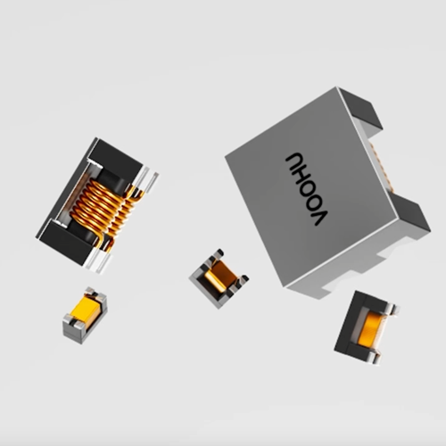
How to choose between single channel and dual channel BMS isolation transformer? 600–1600V operating voltage, CMC and daisy chain break positioning | VOOHU
How to choose between single channel and dual channel BMS isolation transformer? 600–1600V operating voltage, CMC and daisy chain break positioning | VOOHU
How to choose between single-channel and dual-channel BMS isolation transformers? First, look at whether the AFE daisy chain uses one communication path, or whether two independent paths need to be reserved for two-way communication or ring connections. Single-channel products are suitable for single-channel isolated nodes and straight-line links with clear structures; dual-channel products can carry two isolated channels in one device, making it easy to compress the layout and organize forward and reverse links. However, the dual channel itself will not automatically bring fault tolerance. The bypass, diagnosis and recovery after the link is broken are still determined by the AFE, bridge chip, connection method and software strategy.
VOOHU BMS isolation transformerSingle-channel and dual-channel products are available, with selected samples covering operating voltages from 600–1600VDC and including configurations with and without CMC. When selecting, you can first screen by the number of channels and the highest continuous operating voltage, then check the isolation withstand voltage and its VAC or VDC unit, and finally verify the communication margin using the actual wiring harness, terminal network and common-mode interference conditions. This not only avoids blindly amplifying components for a higher number, but also allows sample testing to be closer to the real link in the battery pack.
1. How to choose between single channel and dual channel of BMS isolation transformer: first draw the communication path clearly
Single channel suitable for point-to-point isolation all the way
In a linear daisy chain, there is usually an independent differential communication link between adjacent sampling boards. If only one isolation boundary needs to be crossed at a certain location, a single-channel transformer can complete this signal coupling. When laying out, the differential lines should be paired and of equal length, and the transformers, terminals, and AFE communication pins should be placed in a compact area to reduce long branches and unnecessary vias. The advantage of the single-channel solution is that the network is intuitive. When measuring the waveforms at the transmitter, both sides of the transformer and the receiver segment by segment, the fault boundaries are also relatively easy to divide.
Dual channel is suitable for centralized layout of two independent links
When the same sampling board needs to connect upstream and downstream sections, or a ring architecture needs to organize forward and reverse paths, dual-channel products can concentrate two magnetic channels in one package. When evaluating, you still need to check the pins, polarity, terminals and wiring of each channel separately. The dual channels cannot be understood as internal parallel connection or automatic switching. The system can only maintain communication after a link is broken if the AFE and bridge devices support bidirectional or ring communication, the PCB correctly leads out the two paths, and the software also has failover logic.
The number of channels should be determined together with the node connection method.
First mark the main control, bridge device, each sampling board and communication direction on the schematic diagram, and then count the number of independent channels required for each isolation position. If the project only has one-way straight links, dual channels may increase unused pins and wiring area; if you plan to do head-to-tail loopback or bidirectional diagnosis, single-channel devices can also be arranged separately, but the number of devices, assembly and channel consistency need to be re-weighed. The final selection should be based on the actual topology rather than just the number of sampling plates.
2. How to choose the working voltage and isolation withstand voltage of BMS isolation transformer
Operating voltage determines long-term insulation boundaries
The operating voltage corresponds to the potential difference that the device endures over a long period of time during normal operation. When determining this parameter, the highest voltage that may occur continuously in the system should be used, and allowance should be made based on the AFE location, the number of battery strings, the charging limit, and the insulation design rules adopted in this project. 600V, 1000V, 1500V or 1600V products do not directly correspond to the nominal voltage of a fixed battery pack; in the same total voltage system, the long-term potentials endured by different isolation positions may also be different, so it needs to be confirmed one by one according to the actual connection points.
Isolation withstand voltage is the test capability under specified conditions
The isolation withstand voltage is used to confirm that the insulation between windings is maintained within the specified test voltage and time. It is not the same parameter as the long-term operating voltage. When comparing products, the VAC or VDC unit must be retained, and 3100VAC, 4300VDC, and 6300VDC cannot be sorted directly by numerical size. The selection should also take into account the applicable standards for the whole machine, basic or reinforced insulation requirements, altitude, pollution level, creepage distance and electrical clearance. The working voltage and isolation withstand voltage in the VOOHU product table can be used for the first round of screening. The final insulation judgment should still fall into the complete machine design requirements and corresponding product information.
Sample screening first locks boundaries, then compares dimensions and channels
It is recommended to first eliminate products whose operating voltage or isolation withstand voltage does not meet the design boundaries, and then compare the number of channels, CMC configuration, packaging and PCB space among qualified candidates. This avoids the need to first select a product based on its appearance, only to discover later that the long-term operating voltage is insufficient; it also avoids only pursuing the highest isolation value while ignoring whether the channels and wiring are suitable for the existing AFE solution.
3. The difference between BMS isolation transformer with CMC and without CMC: look at the common mode noise path
With CMC, a filter can be added to the common mode interference of the wiring harness.
Long wire harnesses within the battery pack, adjacent high-voltage switch nodes, and ground potential changes between boards can introduce common-mode disturbances to the daisy-chain communication lines. The BMS isolation transformer with CMC provides a common-mode filtering path within the magnetic device, which helps reduce additional devices and shorten sensitive traces. It is suitable for priority use at nodes with long cross-board wire harnesses, obvious common-mode disturbances, or tight layout space. It does not replace termination, ESD protection and differential cabling. The entire link must still be configured according to the AFE reference design.
Without CMC retains freedom for external filtering and compact links
For links with short distances on the same board or with light noise conditions, products without CMC can be evaluated; if the project wants to select a common mode inductor separately, the filter can also be placed closer to the connector or noise inlet. The external solution is easy to adjust the impedance and layout, but it will increase the components, solder joints and area. The absolute advantages and disadvantages of the two solutions are not separated from the circuit conditions. They should be compared based on the receiving end differential waveform, common mode swing, bit errors or PEC errors, and EMC results.
Terminal and center tap connections cannot be copied from other AFEs
Different AFE or bridge devices have their own requirements for transformer inductance, termination resistors, bypass capacitors, center taps and protection devices. After replacing a device or switching to a CMC configuration, you should first go back to the reference design of the chip used and check each network value and connection method. In particular, do not directly copy the terminal parameters of another set of AFE just because the interfaces are both daisy-chained; reflections and common-mode conversion caused by mismatched terminals may manifest as intermittent faults that occur after the temperature, line length, or number of nodes increase.
4. VOOHU 600–1600V BMS isolation transformer selection reference
The following four VOOHU products cover single channel, dual channel, with CMC and without CMC, and can be used to establish sample matrices with operating voltages from 600VDC to 1600VDC. The parameters in the table are used to narrow down the candidate range; after confirming the product, continue to confirm the package, pins, temperature range, and electrical indicators related to the target AFE.
| Application and selection focus | Verifiable VOOHU products | Key parameters and sample verification points |
|---|---|---|
| Single channel; 600VDC operating voltage; hope to integrate common mode filtering | WHS06602A0 | Channel Single; Working Voltage 600VDC; Isolation 3100VAC; CMC Yes. Focus on checking the target insulation level, terminal network and wiring harness common mode interference. |
| Single channel; 1000VDC working voltage; plan to install externally or not use CMC | WHS06808A0 | Channel Single; Working Voltage 1000VDC; Isolation 4300VDC; CMC No. It is suitable for comparing waveforms and EMC of the same board with external filtering solutions. |
| Dual channel; 1500VDC working voltage; high isolation withstand voltage | WHST12B03A0 | Channel Dual; Working Voltage 1500VDC; Isolation 6300VDC; CMC Yes. Focus on verifying two-way pins, polarity, termination, and single point disconnection in ring topologies. |
| Dual channel; 1600VDC working voltage; integrated CMC | WHST12E01E0 | Channel Dual; Working Voltage 1600VDC; Isolation 4300VDC; CMC Yes. Suitable for inclusion in dual-channel sample branches with higher operating voltages, and review of insulation requirements for the entire machine. |
If the focus is on mid-range operating voltage and integrated common-mode filtering, evaluate firstWHS06602A0; 1000VDC single channel and you want external filtering, you can compareWHS06808A0. When facing 1500VDC working voltage and requiring two channels,WHST12B03A0Provides 6300VDC isolation withstand voltage; when the designed operating voltage upper limit reaches 1600VDC, theWHST12E01E0Add samples for testing. The isolation parameter units of the four products are not exactly the same, so VAC and VDC should be kept separately during the review.
5. How to troubleshoot BMS daisy chain disconnection: from fault location to recovery path
First confirm whether the fault occurs on a link or a node
After the link is broken, first read the last node that can respond stably, and then measure outward from the adjacent link. The oscilloscope should simultaneously observe the differential waveforms on the transmitting and receiving sides of the transformer to confirm whether there are complete pulses, obvious attenuation, reflections or common mode lifts. If the sending side is normal but the receiving side is abnormal, focus on checking the transformer welding, terminals, connectors and wiring harness; if there are no valid waveforms on both sides, continue to check the AFE port configuration, power supply, sleep state and communication direction.
Verify bidirectional or ring communications with a single point of disconnect
Systems with bidirectional or ring capabilities can disconnect each section of communication line in turn under controlled conditions, recording forward links, reverse links, fault location and recovery time. The verification goal is not to prove that the dual-channel transformer itself will switch, but to confirm that if the entire topology fails in one segment, the controller can access the node from the other direction as designed and re-establish complete communication when the connection is restored. Only change one breakpoint at a time so that the test results can easily correspond to the schematic position.
Cover wire length, node number, temperature and interference together
The daisy chain is stable with short lines and a small number of nodes, but it does not mean that the mass production wire harness, maximum number of nodes, and high and low temperature conditions still have the same margin. The sample phase should cover the longest harness, most nodes, lowest and highest operating temperatures, power-up and wake-up processes, and observe communications near typical high-voltage switching actions. Record error counts, retries, lost nodes, recovery times, and waveform changes to determine whether the problem is caused by magnetics, terminals, wiring harnesses, or system timing.
Review EMC and insulation testing after product replacement
Changes in channel count, CMC, or packaging can simultaneously affect routing, parasitic parameters, and common-mode current paths. After candidate products pass basic communications, they must be retested for conductive and radiated immunity, static electricity, and transient items specified by the project, and insulation-related verification must be completed. The test voltage, duration, judgment standards and safety protection must adopt project-approved methods, and the test conditions of the whole machine should not be directly derived from just an isolation number.
6. Frequently Asked Questions (FAQ)
How to choose between single channel and dual channel BMS isolation transformer?
Select according to the number of independent paths required for each isolation location: a single channel is usually used for a point-to-point path; dual channels can be evaluated when the upstream and downstream, forward and reverse paths need to be centralized. Ring faults are still implemented by the AFE, bridge devices, PCB and software.
What is the difference between BMS isolation transformer with CMC and without CMC?
Products with CMC add a common-mode filter path within the device, which can reduce external components; products without CMC make it easy to place the external filter at the actual noise entrance, and are also suitable for compact short links on the same board. Both solutions require proper termination, differential cabling and protection, confirmed with waveform and EMC testing.
Can we only look at the larger one for the working voltage and isolation withstand voltage?
Can't. The operating voltage describes the long-term operating boundary, the isolation withstand voltage describes the insulation test capability under specified conditions, and VAC and VDC must be distinguished. Only after both items meet the insulation design requirements of the complete machine can the product enter sample comparison.
How to troubleshoot BMS daisy chain disconnection faster?
First find the last normal node, measure the differential waveforms on both sides of the adjacent transformer, and check the welding, terminals, connectors, wire harnesses and AFE ports. If bidirectional or ring communication is supported, use single point disconnection to confirm reverse access, location and recovery.
7. Conclusion: Make the channel, insulation and anti-interference consistent with the actual topology
The selection of BMS isolation transformer should start from the communication path, and then converge on the operating voltage, isolation withstand voltage, CMC and packaging. VOOHU single-channel and dual-channel products cover operating voltages of 600–1600VDC, allowing clear sample combinations to be established for different daisy chain nodes. Only by putting each product into the target AFE, terminal network and real wire harness, and completing communication, link disconnection, temperature, EMC and insulation verification, can we determine a solution more suitable for mass production systems.