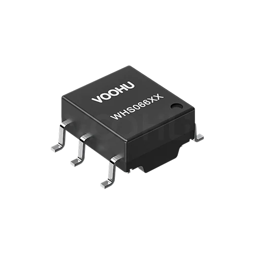
WHS06602A0 Single Working Voltage600 Isolation3100VAC BMS ISOLATION TRANSFORMER
Request a Quote
Leave your details and we will send a tailored volume quote.
Our sales team will contact you within 1 business day.
Contact Sales
Reach our sales team for pricing and lead time.

Submitted
We have received your request. Our sales team will contact you within 1 business day.


For technical assistance, please click the button below to add customer service or visit the sample request page to fill out the form. We will serve you as soon as possible.
Technical Support Email: fae.thorne@voohu.cn Phone: +86 400-1048-018
For more details, please visit the Download Center to get documents or click the button below to add customer service. We will serve you as soon as possible.


For small-volume orders, you can place orders directly on VOOHU Shop. We support VAT general/special invoices with a convenient and efficient process.
For technical assistance or sample requests, please click the button below to add customer service or visit the sample request page to fill out the form. We will serve you as soon as possible.
Customer Service Email: song.lei@voohu.cn Phone: +86 180 2130 1120
VOOHU Electronics holds ISO 9001:2015 international quality management system certification, ISO 14001:2015 environmental certification, RoHS environmental certification, REACH certification, and CE certification.
On the VOOHU official website, you can quickly select products online through product categories or parameter filters (such as data rate, package type, operating temperature, current, etc.). You can also visit the "Solutions" page to view recommended solutions that match your needs. For further support, you can directly contact the technical support team and provide your application scenario — we will accurately recommend the optimal solution for you.
In a BMS, an isolation transformer is mainly used for:
(1) High/low-voltage isolation—providing isolated power between the high-voltage battery-pack-side circuits (such as the AFE) and the low-voltage control circuitry, preventing high-voltage leakage from damaging the low-voltage side and ensuring personal safety.
(2) Digital communication isolation—transmitting sampled data between the battery-monitoring chip and the main control MCU via isolated coupling (such as isolated CAN), eliminating common-mode interference and ground loops; this is more common than transmitting analog signals directly through a transformer. In addition, isolation transformers can also be used for signal-feedback isolation in auxiliary power supplies.
A daisy chain (such as isoSPI or a UART daisy chain) connects multiple AFEs end to end in series, so only one pair of isolated signal lines is needed to connect all slave boards. Compared with a parallel bus or star connection, the daisy chain has clear advantages:
(1) It greatly reduces wiring harnesses and connectors, lowering cost and weight.
(2) Electrical isolation is easier to achieve in high-voltage series battery packs (isolation only needs to be done once at the head of the chain).
(3) It supports relatively long-distance transmission. The drawback is that a single-point failure affects downstream nodes, so a fault-tolerance mechanism must be designed.
Because cells differ in manufacturing process, temperature gradient, and aging rate, voltage inconsistencies arise during series charge/discharge. Without balancing, lower-capacity cells will fill up or empty first, reducing the usable capacity of the whole pack and even causing overcharge/over-discharge safety risks. Balancing is divided into passive balancing (dissipating energy through resistors) and active balancing (transferring energy through capacitors or transformers); the goal is to keep cell voltages consistent and extend battery life.
(1) Choose AEC-Q200-certified transformers to ensure automotive-grade reliability.
(2) Use dual-winding or redundant designs to prevent a single-point failure from causing isolation failure. (3) Perform 100% production-line testing of withstand voltage and partial discharge, with a test voltage typically 1.2-1.5 times the rated isolation voltage.
(4) Monitor the transformer's secondary output voltage and immediately trigger a fault report if an abnormality occurs.
(5) Pair with isolation-fault detection circuits (such as missing-resistor detection or window comparators) to meet ASIL B/C requirements.