PoE PSE vs PD: What Each End Does and Which Magnetics It Needs
In Power over Ethernet (PoE), the PSE (power sourcing equipment) is the end that supplies power, such as a PoE switch port or a midspan injector, and the PD (powered device) is the end that receives it, such as an IP camera, a wireless access point or an IP phone. Both ends carry data through LAN transformers, and the DC power is applied to, and taken from, the center taps of those transformers, so each end needs a data transformer rated for DC port current. Only the PD normally adds a second magnetic part: a power transformer in the DC-DC converter that turns the cable voltage into the device's supply rail. VOOHU supplies both kinds: PoE-rated LAN transformers and power transformers in EP13 and EFD20 cores.
What does PoE PD mean, and what is a PSE?
TI's TPS23881 PSE controller data sheet defines the two roles: the host or midspan equipment that supplies power is the power source equipment (PSE), and the load at the Ethernet connector is the powered device (PD). In practice the PSE is a switch's PoE port or a midspan injector, and the PD is the device at the far end.
How is the PoE handshake done between PSE and PD?
The PoE overview in TI's TPS2373 PD interface data sheet describes an idle state and three operating states: detection, classification and operation. During detection, the PSE leaves the cable unpowered while it periodically looks for a valid PD signature; Type 3 and Type 4 PSEs also run a connection check to see whether the PD presents the same or independent signatures on each pairset. If a valid signature is present, the PSE may ask how much power the PD requires, which is classification, and then powers the PD if it has enough capacity. Once running, the PD must present a maintain power signature (MPS); if the PSE loses it, the port is turned off and returns to idle.
PoE PD classes: how Type and Class fit together
The same data sheet summarises the naming. A device compliant with IEEE 802.3-2012 is a Type 1 (Class 0–3) or Type 2 (Class 4) device, and the higher-power devices with enhanced classification are Type 3 (Class 5, 6) or Type 4 (Class 7, 8); Type 3 also includes 4-pair-capable Class 0–4 devices. Type 1 and Type 2 PSEs apply voltage to one set of pairs at a time, while Type 3 and Type 4 PSEs may power one or both sets. The power allotted to each class is set by IEEE 802.3, which TI advises should always be referenced for design decisions. For what four-pair power means for the data transformer, see our guide to IEEE 802.3bt PoE magnetics; for which pins carry power in Mode A and Mode B, see PoE pinout: Mode A vs Mode B.
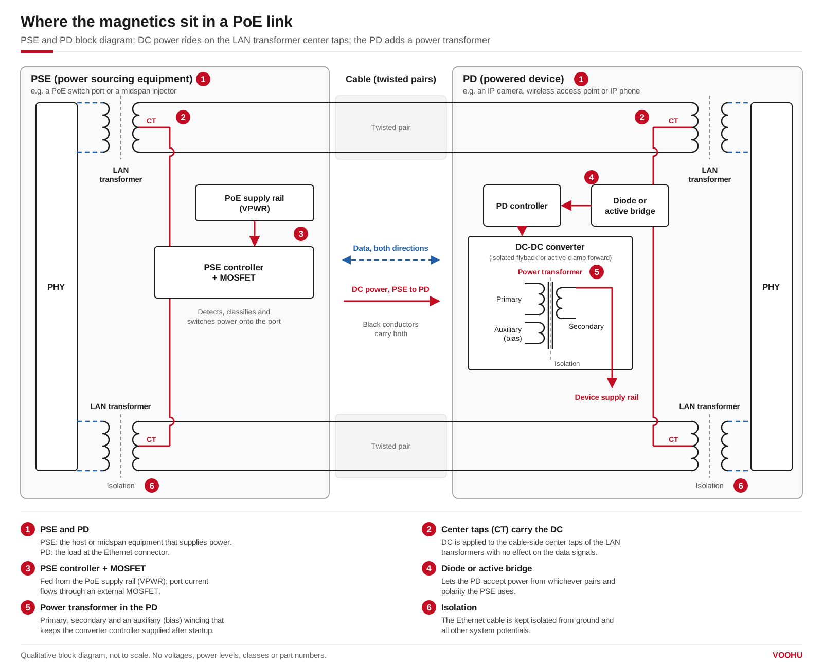
Where the magnetics sit in a PoE link. Both ends use LAN transformers whose center taps carry the DC power; only the PD adds a power transformer in its DC-DC converter. Simplified diagram.
What is inside a PoE PSE port: controller, power rail and data transformer
In a PSE built on the TPS23881, each channel provides detection, classification, protection and shutdown, and the port current flows through an external MOSFET driven by the controller. The PoE voltage comes from a separate supply rail, VPWR. The TPS23881 data sheet gives a supported VPWR range of 44 V to 57 V, and asks for a supply with a 50 V minimum output for 30 W to 60 W ports and a 52 V minimum for Type 4. So a PSE port does not need a power transformer of its own: the voltage is produced by the system power supply and switched onto the cable.
What the PSE port does need is a data transformer that can carry DC. TI states that a DC voltage can be applied to the center tap of the transformer with no effect on the data signals. For its IEEE 802.3bt PSE controller, TI adds that the data transformer must be rated to operate within the 802.3bt standard in the presence of the DC port current. In general, choose a data transformer rated for the DC current of the PoE type your port supplies; it may also be integrated into the RJ45 connector. For layout and thermal questions in switches with many ports, see PoE switch PSE multiport design.
What is inside a PoE PD: controller, DC-DC converter and power transformer
The PD mirrors the PSE on the data side. Power arrives at the cable-side center taps of the PD's LAN transformers, or on the spare pairs in some 10/100 designs, and passes through input diode or active bridges, which let the PD accept power from any of the possible PSE configurations. It then reaches the PD interface controller, such as the TPS2373, which presents the detection and classification signatures and then connects power to the converter.
TI notes that a PD controller is typically followed by a power supply such as an isolated flyback or active clamp forward converter, or a non-isolated buck converter. In the isolated versions, the converter needs a power transformer, and this is the magnetic part a PSE port does not have. The same data sheet also shows that, after startup, the DC-DC controller can be supplied from a bias winding of the DC-DC converter's power transformer. When you compare PD power transformers, start with the primary input range, the output voltage and current, and the auxiliary winding. Surge protection and the rest of the PD front end are covered in PoE PD circuit design and surge protection.
PoE PSE and PD transformers: which magnetics does each end need?
The first table sorts the magnetics of a PoE link by where they are used. This grouping is ours, by application: the datasheets do not label any part as a PSE part or a PD part, and a PoE-rated LAN transformer does the same data job at either end. The second table gives the VOOHU examples, with values quoted as printed on each datasheet.
| End | Data magnetics (signal pairs) | Power magnetics |
|---|---|---|
| PSE (switch port, midspan) | PoE-rated LAN transformer; DC is applied at the cable-side center taps. Examples: WHDG24102PTG, WHSG48008-3PG | None at the port; the PoE voltage comes from the system supply rail (VPWR) and is switched by the PSE controller |
| PD (camera, access point, phone) | PoE-rated LAN transformer of the same kind; DC is taken from the cable-side center taps. Same examples | Power transformer in the DC-DC converter, when the converter is isolated. Examples: WHEP13779 (EP13), WH300F-24L (EFD20) |
| Part | Used here as | Form | What the datasheet states |
|---|---|---|---|
| WHDG24102PTG | Data transformer, either end | Gigabit LAN transformer, through-hole (DIP) | "IEEE802.3at compliant performance-720mA balanced current"; chip-side (TCT1–4) and cable-side (MCT1–4) center taps brought out separately; isolation 1500 VAC, 1 mA, 60 s |
| WHSG48008-3PG | Data transformer, either end | Gigabit LAN transformer, surface-mount (SMD) | "Each channel support 600mA DC current, full channels support 1200mA DC current"; isolation 1500 VAC, 1 mA, 60 s |
| WHEP13779 | PD power transformer | EP13 | Primary 36~57 V; secondary 12 V, 2.1 A; auxiliary 13.3 V; −40 °C to +125 °C |
| WH300F-24L | PD power transformer, 24 V output | EFD20; the datasheet calls it a flyback transformer | Input 36~72 V, 250 kHz; output 24 V, 1.25 A; auxiliary 12 V; −40 °C to +125 °C |
Read the PoE current lines exactly as written. The two data transformers state DC current in their own terms ("balanced current"; "each channel" and "full channels"), and neither datasheet defines it per pair, so do not convert these figures into watts. Another EP13 option is the ST1388WH, with a 12 V, 2 A output winding. Our FAE team can tell you which PoE type your PSE or PD needs and which of these parts fits your controller.
More parts: EP13 PoE power transformers, EFD20 power transformers, the 10/100/1000BASE-T LAN transformer selector and the gigabit LAN transformer family.
产品WHDG24102PTG
方案/solution-poe/
FAQ
Q1: Is PoE+ 24 V or 48 V?
Neither figure is exact, but IEEE PoE, including PoE+, is not a 24 V system. TI's TPS23881 data sheet explains that a relatively high voltage, approximately 50 V, is used to keep currents low and limit IR drops in the cable. Table 6 of the TPS2373 data sheet lists a minimum PSE static output voltage of 44 V for IEEE 802.3-2012 Type 1 and 50 V for 802.3at Type 2 (PoE+), with the PD static input voltage going up to 57 V. A 24 V supply is outside these limits, so a 24 V "passive PoE" injector is not an IEEE 802.3 PSE.
Q2: Is PoE galvanically isolated?
It is meant to be. As the TPS2373 data sheet puts it, the IEEE standards require the Ethernet cable to be isolated from ground and all other system potentials. On the signal pairs, the LAN transformers provide that isolation at both ends. On the PD's power path, it is normally provided by an isolated DC-DC converter and its power transformer.
Q3: When is it allowed to use non-isolated PoE?
TI lists a non-isolated buck converter as one of the usual power stages after a PD controller, so non-isolated designs exist. Whether one is acceptable depends on whether anything else in your device can connect to ground or to other equipment, since the cable must stay isolated from them. Check this against IEEE 802.3 and your product's safety standard; our FAE team can help review whether an isolated power transformer is needed.
Q4: Can the same LAN transformer be used at the PSE and at the PD?
The data transformer does the same job at both ends: it carries the Ethernet signals and lets DC pass through its center taps. The datasheets of the two VOOHU examples above, WHDG24102PTG and WHSG48008-3PG, do not tie them to either end. Check the DC current statement against the PoE type of your design, and ask our FAE team to confirm a part for your PSE or PD controller.
Get help choosing PoE magnetics for your PSE or PD
Designing a PoE switch port or a powered device? Send us the PSE or PD controller you plan to use, the PoE type or class, the port speed and the output rail you need through our sample and support form. Our FAE team can suggest a PoE-rated LAN transformer and, for a PD, a power transformer, and help check the design. Samples are available for evaluation, and selected parts are free of charge. Our FAE team will be glad to confirm the options for your project. VOOHU supplies RJ45 and SFP connectors, LAN and PoE transformers and common mode chokes from Suzhou, China, to more than 1,500 customers.
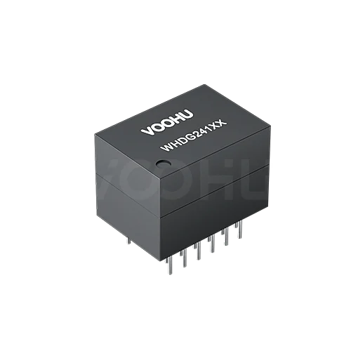 WHDG24102PTG Single Port DIP Gigabit Base-T PIN24 PoE 720mA LAN Transformer
> View Details
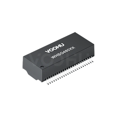 WHSG48008-3PG Dual Ports SMD Gigabit Base-T PIN48 4PPoE LAN Transformer
> View Details
 WHEP13779 Power 25.2W, Output voltage 12V, Output current 2.1A, Turns ratio 26:10:09; ±3% POE power transformer
> View Details