Power over Ethernet carries DC on the RJ45 contacts, two pairs at a time. Alternative A (called Mode A at the powered device) uses contacts 1-2 and 3-6; Alternative B (Mode B) uses contacts 4-5 and 7-8. Each of these pair sets has one positive pair and one negative pair, and the current enters and leaves each pair through the cable-side center tap of its LAN transformer winding. IEEE 802.3bt 4-pair power uses both pair sets at once and is required for Class 5 and higher. On the VOOHU WHSM24706C2 LAN transformer, the four cable-side center taps are pins 24, 21, 18 and 15.
#What pins are used for PoE?
The standard assigns power to contact pairs, not to wire colors. The table shows the PoE pin assignment for each powering option and what the same contacts do for data.
Contact pairs per the Ethernet Alliance overview of IEEE 802.3bt (2019), Figure 25. T568A or T568B wiring changes only the wire colors, not these contact pairs.
Which pair is positive? Many cable charts show contacts 1-2 as positive and 3-6 as negative, but that is only one option. Both conductors of a pair are always at the same polarity, and according to the Ethernet Alliance overview, Type 1 and Type 2 PSEs may use any of the 2-pair configurations listed for them, Type 3 PSEs may use any of four polarity permutations, and Type 4 PSEs only one. PDs of every Type are required to support any polarity configuration, so a PD needs rectification at its input: two full diode bridges or an active rectifier.
#PoE Mode A vs Mode B: what is the difference?
Both names describe the same two pair sets. IEEE 802.3 calls them Alternative A and Alternative B at the power sourcing equipment (PSE), such as a switch or injector, and Mode A and Mode B at the powered device (PD), such as a camera, access point or phone. When a link is powered over two pairs, the PSE powers either Alternative A or Alternative B.
The practical difference depends on the data rate. On a 10BASE-T or 100BASE-TX link, Alternative A shares the two data pairs, while Alternative B uses the two pairs that carry no data. On 1000BASE-T and faster links all four pairs carry data, so either way the power rides on data pairs through the transformer center taps. Type 3 and Type 4 PDs are required to accept both 2-pair and 4-pair power.
#How does 4-pair PoE (802.3bt) use the pins?
In 4-pair operation both pair sets are powered: two pairs at the positive voltage carry current to the PD, and two pairs at the negative voltage carry the same total current back. A PSE that assigns Class 5 or higher must power all four pairs. The two pairs of the same polarity are in parallel, so the current does not divide exactly evenly between them; the Ethernet Alliance overview calls this pair-to-pair current unbalance. For the per-pair currents the magnetics must carry, see IEEE 802.3bt PoE magnetics selection.
#How are the LAN transformer center taps connected for PoE?
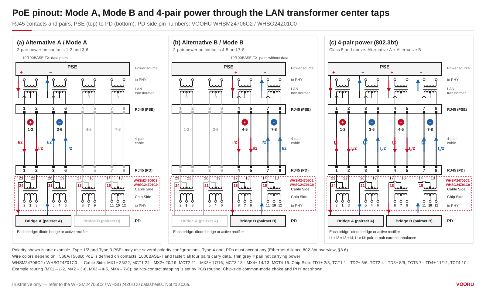
PoE wiring diagram: Mode A, Mode B and 4-pair power through the LAN transformer center taps. Pin numbers are for the VOOHU WHSM24706C2 and WHSG24Z01C0; polarity shown is one example. Illustrative only; see the datasheet.
Each pair ends in one winding of the LAN transformer. The cable-side winding has a center tap, and that is where the PSE injects the supply voltage and where the PD takes it off. Both wires of a pair sit at the same DC voltage, so the differential data signal passes through the transformer while the DC flows in at the center tap and out along both wires of the pair.
A discrete LAN transformer for PoE therefore brings each cable-side center tap out on its own pin. The VOOHU WHSM24706C2 (10GBASE-T) and WHSG24Z01C0 (1000BASE-T) use the same pin numbers, printed on their datasheet schematics with Cable Side and Chip Side labels:
Source: WHSM24706C2 and WHSG24Z01C0 datasheet schematics. Each center tap has its own pin, and there is no termination inside the transformer.
Which RJ45 contact pair each channel serves is set by your PCB routing, not by the transformer. If you route MX1+ and MX1− (pins 23 and 22) to contacts 1 and 2, pin 24 becomes the center tap of the 1-2 pair. For Alternative A, the center taps of the 1-2 pair and the 3-6 pair go to opposite supply rails; for Alternative B, the center taps of the 4-5 and 7-8 pairs do the same. The transformer datasheet does not prescribe this; it follows from the PSE or PD design. A common 4-pair PSE implementation, as the Ethernet Alliance overview describes, ties the positive pairs directly to the supply and puts a switch and current measurement on each negative pair.
Pin names are not consistent across VOOHU packages, so go by the Cable Side and Chip Side labels on the datasheet rather than by net names. On the dual-port WHSG50002P1, for example, the cable-side center taps are named TCT: TCT1 to TCT4 on pins 2, 5, 8 and 11, and TCT5 to TCT8 on pins 15, 18, 21 and 24. Its chip-side center taps are named MCT, on pins 49, 46, 43, 40, 36, 33, 30 and 27. If a schematic does not mark the sides, ask our FAE team before you assign PoE pins.
#Where are the PoE pins on an RJ45 jack with integrated magnetics?
With integrated magnetics, the transformers are inside the jack and the datasheet brings the cable-side center taps out as power pins. The VOOHU SYT4A11Q855HWA10DPB1359 names them after the contacts they serve: VC12 (pin 13) for contacts 1-2, VC36 (pin 14) for 3-6, VC45 (pin 15) for 4-5 and VC78 (pin 16) for 7-8. VC12 and VC36 are therefore the Alternative A pair set, and VC45 and VC78 the Alternative B pair set. Each VC line also reaches the jack's built-in termination through a 22 nF capacitor in series with a 75 Ω resistor, ending in a 1000 pF / 2 kV capacitor to the shield. The PHY-side center taps are separate pins: 1, 9, 10 and 6. How to connect the VC pins on the PSE or PD side depends on the jack's datasheet, so ask our FAE team to confirm it for your design.
To compare other jacks, use the RJ45 selector filtered to integrated magnetics and check the PoE column, or read PoE integrated magnetic RJ45 selection. Discrete LAN transformers with a PoE rating are in the LAN transformer selector.
#FAQ
Does PoE need all 8 wires?
Not always. Type 1 and Type 2 PoE (802.3af and 802.3at) power only two pairs, so a 10/100BASE-TX link powered on Alternative A uses only contacts 1, 2, 3 and 6. 802.3bt Class 5 and higher powers all four pairs, and 1000BASE-T needs all eight wires for data anyway.
Is PoE 12V or 48V?
Neither exactly. IEEE 802.3 PSEs output 44–57 V for Type 1, 50–57 V for Type 2 and Type 3, and 52–57 V for Type 4. Lower voltages such as 12 V or 24 V are passive PoE, which is outside IEEE 802.3.
Can a Mode A device work with a Mode B switch?
Yes, if the device follows IEEE 802.3. PDs of every Type are required to support any of the PSE pinout and polarity configurations, which is why they rectify both pair sets. Passive PoE devices do not follow this rule, so check their documentation.
Should you use T568A or T568B for PoE?
Either works. PoE is defined on contacts 1-2, 3-6, 4-5 and 7-8, and T568A and T568B only swap the colors of two pairs. Use the same scheme at both ends of a straight-through cable.
#Have your PoE port pinout checked
Send us your schematic or the LAN transformer or RJ45 jack you plan to use, with the PSE or PD side and the PoE Type, through the sample and support request form. Our FAE team can check which center-tap pins go to which contact pair and suggest a VOOHU LAN transformer or integrated-magnetics RJ45 jack for the port. Samples are available for evaluation, and selected parts are free of charge. Our FAE team will be glad to confirm the options for your project.
VOOHU supplies RJ45 and SFP connectors, LAN and PoE transformers and common mode chokes from Suzhou, China, to more than 1,500 customers.
Need a quote, samples or selection support?
Part number WHSM24706C2 is filled in for you. Add the quantity and lead time and submit. Our FAE team will be glad to confirm the options for your project.
Before you order: samples, MOQ, lead time and import duties in our ordering guide →