RS-485 Circuit Design: Transceiver, Termination, Bias, Isolation, Common Mode Choke and TVS
RS-485 Circuit Design: Transceiver, Termination, Bias, Isolation, Common Mode Choke and TVS
An RS-485 node needs five things around the transceiver: a 120 Ω termination resistor at each of the two ends of the bus and nowhere else, a failsafe bias that holds the idle bus at +200 mV or more, isolation when the nodes do not share a ground, a TVS that clamps ESD and surges on the A and B lines, and often a common mode choke to reject common-mode noise. Keep A and B as one twisted, matched pair, put the protection at the connector, and keep every part compatible with the −7 V to +12 V common-mode range the standard sets for receivers. VOOHU supplies signal-line common mode chokes, including 3225 parts rated 550 Ω typical at 10 MHz, and TVS arrays; our FAE team can check whether they suit your bus speed, common-mode range and transceiver.
What does an RS-485 node circuit include?
RS-485 (TIA/EIA-485-A) is a balanced, differential bus. Most nodes run half duplex on one twisted pair: the transceiver drives A and B when it transmits and listens the rest of the time, switched by its DE and RE̅ pins. The standard sets the numbers the rest of the circuit has to respect:
- a receiver threshold of ±200 mV, so the bus must sit at least 200 mV away from zero to read a defined state;
- a common-mode range of −7 V to +12 V, which covers ground differences between nodes;
- up to 32 unit loads on one bus, more with fractional-load transceivers;
- cable runs up to about 1200 m at lower data rates, on twisted pair with a characteristic impedance of about 120 Ω.
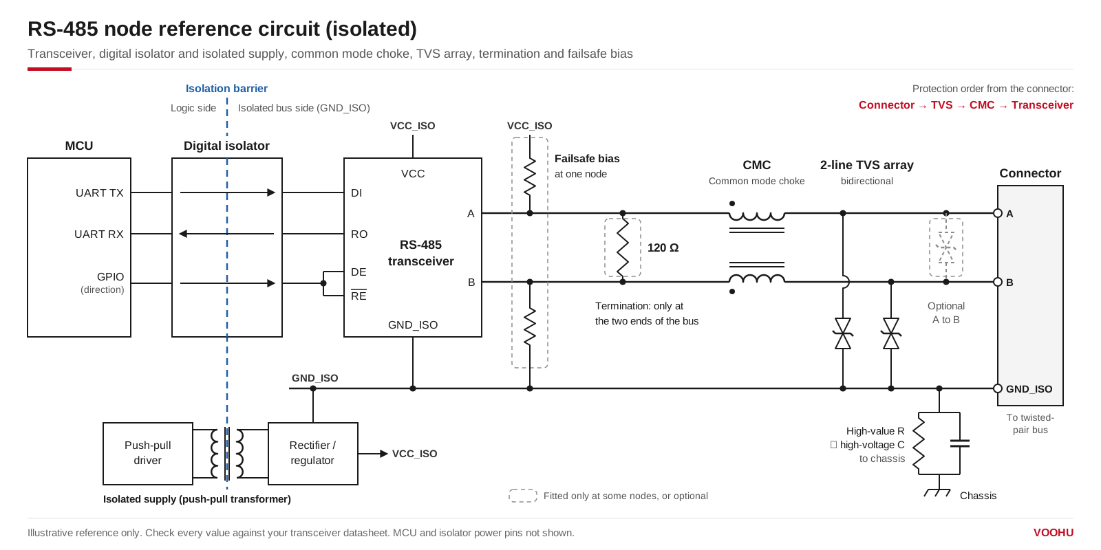
RS-485 node reference circuit: MCU, digital isolator and isolated supply, transceiver, common mode choke, TVS, termination and failsafe bias. Reference only; check every value against your transceiver datasheet.
From the MCU outwards, a typical isolated node has a digital isolator and an isolated supply, the transceiver, a common mode choke, a TVS array and the connector. The termination resistor and the bias resistors sit on the bus side, at the nodes where the bus needs them.
How do you choose the RS-485 transceiver?
Start from the bus, not the MCU. Check the supply voltage (3.3 V or 5 V), the data rate against the cable length, the unit load (a 1/8 unit-load part lets more nodes share the bus), whether the receiver has a built-in failsafe for an idle or open bus, and the ESD and fault ratings of the A and B pins. If the nodes can sit at different ground potentials, consider a transceiver with integrated isolation. The absolute maximum rating of the A and B pins is also the limit your TVS has to clamp below.
Does RS-485 need a termination resistor, and what value?
On most buses, yes. A signal reaching the open end of the cable reflects back and causes ringing and bit errors. A resistor across A and B equal to the cable's characteristic impedance, usually 120 Ω, absorbs that energy. Place one at each of the two physical ends of the bus and none on the nodes in between: extra terminations load the drivers and shrink the differential voltage. On a short, slow link, reflections may settle before the receiver samples, which is why some short point-to-point links leave termination out; check your transceiver vendor's guidance before you do.
A split termination, two 60 Ω resistors in series with a capacitor from their midpoint to ground, keeps the 120 Ω differential match and also filters common-mode noise.
For the power rating, use P = V²/R with the highest differential voltage your driver can hold on the bus. Suppose a 5 V driver could hold the full supply across a 120 Ω terminator: that is about 0.21 W. In normal operation the differential voltage is lower, but sizing for this case covers a stuck driver.
How do you bias an idle RS-485 bus (failsafe biasing)?
When no node is driving, the terminations pull A and B together, the differential voltage falls inside ±200 mV and the receiver output is undefined, so the UART can see false start bits. There are two fixes. The simpler one is a transceiver with a built-in failsafe threshold that reads an idle, shorted or open bus as logic high. The other is a pull-up on A and a pull-down on B at one node, sized so that the idle bus sits at +200 mV or more.
To size the bias, treat the two terminations as one 60 Ω load. Suppose a 5 V supply and a 200 mV target: the pull-up and pull-down together must be no more than 5 V × 60 Ω ÷ 0.2 V − 60 Ω = 1440 Ω, so 680 Ω each gives about 211 mV. Leave margin for resistor and supply tolerance, and remember that bias resistors add load the drivers must carry. Check the A and B naming on your transceiver datasheet before you wire the bias: some vendors swap the labels.
When do you need an isolated RS-485 circuit?
Isolate the node when its ground can differ from other nodes by more than the common-mode range allows, as between buildings, on long runs or next to motor drives, or when a safety barrier is required. There are two common architectures: a digital isolator on the DI, RO, DE and RE̅ lines plus a standard transceiver, or a single isolated transceiver. Either way the bus side needs its own supply, often built with a push-pull driver and a small transformer; VOOHU suppliespush-pull transformerssuch as theWHST06D02A0(for its isolation rating, see the datasheet and confirm with our FAE team). The isolated ground is usually tied to chassis through a high-value resistor in parallel with a high-voltage capacitor, which drains static charge without creating a ground loop.
Do you need an RS-485 common mode choke, and how do you choose one?
Add an RS-485 common mode choke when the node sits near variable-frequency drives, motors or switching supplies, or when the cable radiates and the product fails its emissions test. A common mode choke has two windings on one core. The data signal flows in opposite directions in the two windings, so its flux cancels and it passes almost unaffected; noise that flows in the same direction on both lines sees a high impedance and is attenuated. The choke works alongside the TVS and the termination, not instead of them.
When you compare chokes, check:
- Common-mode impedance and its test frequency.Datasheets state impedance at different frequencies, often 10 MHz or 100 MHz. Compare parts only at the same frequency, and pick the frequency closest to the noise you need to remove.
- Rated current and DC resistance.RS-485 currents are small, but DC resistance adds to the loop that sets your differential voltage.
- Rated voltageagainst the highest voltage the bus can see, including the common-mode range and faults.
- Inductance and leakage inductance, which affect how much the choke shapes the data signal at your bit rate.
- Size and temperature range.
VOOHU signal-line common mode chokes come in two families with different test frequencies:
| Part | Impedance at 10 MHz | Impedance at 100 MHz | Inductance | DCR max | Rated current max | Rated voltage max | Size | Operating temperature |
|---|---|---|---|---|---|---|---|---|
| WHAC-3225B-110U0 | 300 Ω min / 550 Ω typ | Not specified | 11 µH (+50/−30%); leakage 50 nH typ | 0.8 Ω | 300 mA | 80 V | 3225 | −55 to +150 °C |
| WHAC-3225B-101U0 | 2200 Ω min / 5100 Ω typ | Not specified | 100 µH | 4.9 Ω | 150 mA | 80 V | 3225 | −55 to +150 °C |
| WHLC-2012A-102T0 | Not specified | 1000 Ω typ | Not specified | 1.3 Ω | 300 mA | 50 Vdc | 2012 (0805) | −40 to +105 °C |
| WHLC-2012A-900T0 | Not specified | 90 Ω typ | Not specified | 0.35 Ω | 300 mA | 50 Vdc | 2012 (0805) | −40 to +105 °C |
The WHAC-3225B-U0 datasheet lists CAN-FD, CAN, A2B and other differential signal lines, including industrial PLC data lines. None of these datasheets names RS-485, so before you design one in, ask our FAE team to check it against your bus data rate and common-mode range.
As a starting point: where the noise is at lower frequencies, as from motor drives, the WHAC-3225B parts give you a common-mode impedance specified at 10 MHz; for a compact node where the problem is higher-frequency emissions, the WHLC-2012A parts in 0805 are specified at 100 MHz. Browse the3225 signal-line chokesor the2012 (0805) signal-line chokesin the selector.
How do you choose a TVS diode for RS-485 protection?
Because the bus swings both ways around ground within the −7 V to +12 V common-mode range, use bidirectional TVS diodes whose working voltage stays above the highest voltage the line sees in normal use, so they never conduct during communication. Then check that the clamping voltage at your test current stays below the absolute maximum rating of the transceiver's A and B pins. Connect one TVS from A to ground and one from B to ground; some designs add one across A and B.
TheWHALD30E2Bcovers both lines in one SOT-23. Its parameters: bidirectional, 30 V working voltage, 31 V minimum breakdown at 1 mA, clamping voltage 37 V typical at 1 A and 55 V typical at 8 A (8/20 µs), 8 A peak pulse current, 0.9 pF typical capacitance and ±30 kV contact ESD (IEC 61000-4-2). Its clamping voltage is well above the absolute maximum rating of many standard 3.3 V and 5 V transceivers, so it suits transceivers whose bus pins are rated for high fault voltages; for a standard transceiver, ask our FAE team for a lower-voltage option. Before using it on RS-485, ask our FAE team to confirm it against your transceiver's bus-pin ratings and your common-mode range. More bidirectional parts are in theTVS and ESD selector.
How should you lay out the RS-485 front end?
- Place the protection at the connector in this order: connector, TVS, common mode choke, transceiver, so the TVS returns surge current to ground before it reaches the choke. Some designs put the choke first so that its impedance limits the current into the TVS; if you do, check that the choke's rated voltage covers the surge.
- Give each TVS a short, wide return to the bus-side ground.
- Route A and B as a differential pair: symmetrical, equal length, close together.
- Keep the isolator close to the MCU so the logic traces on the controller side stay short, and keep the bus-side ground and supply inside the isolated area.
- Fit termination only at the two end nodes and the bias at one node, usually the master.
For reference schematics and the component list for an RS-485 interface, see theRS-485 solution page; for the CAN bus equivalent, seeCAN bus circuit design.
产品WHAC-3225B-110U0
产品WHALD30E2B
方案/solution-rs485/
FAQ
Q1: Does RS-485 need a ground wire?
Yes, in most installations. The receiver works only while the common-mode voltage between nodes stays within −7 V to +12 V, and a reference or signal-ground conductor keeps the node grounds close enough. If the grounds cannot be held that close, isolate the node instead of relying on the cable shield.
Q2: Where should RS-485 termination resistors be placed?
Across A and B at the two physical ends of the bus cable only, even if the master sits mid-line; keep the stubs to each node short.
Q3: Does RS-485 need twisted pair, and does it need to be shielded?
Use twisted pair: twisting keeps noise common to both wires, where the receiver and a common mode choke can reject it. Shielding is not required by the standard, but it helps on long runs and near drives and motors.
Q4: Will a common mode choke distort the RS-485 signal?
A choke passes the differential data signal largely unchanged, because the signal flux cancels in its core. Its leakage inductance and DC resistance still act on the differential signal, so check them against your bit rate and the differential voltage you need at the far end. For example, the WHAC-3225B-110U0 lists 50 nH typical leakage inductance and 0.8 Ω maximum DC resistance.
Get help checking your RS-485 front end
Send us your bus data rate, cable length, node count, common-mode range and the ESD or surge level you need to pass in thesample and support request form. Our FAE team can check common mode chokes and TVS arrays against those numbers and against your transceiver's bus-pin ratings. Samples are available for evaluation, and selected parts are free of charge. Our FAE team will be glad to confirm the options for your project.
VOOHU supplies common mode chokes, LAN and PoE transformers, RJ45 and SFP connectors and TVS, ESD, GDT and MOV protection devices from Suzhou, China, to more than 1,500 customers.
 WHLC-2012A-900T0 100/1000BASE-T Cap+CMC Size2012(0805) Impedance(Ω)90 non-PoE Chip LAN
> View Details
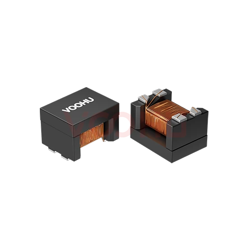 WHAC-3225B-110U0 Inductance11uH RDC0.8Ω Leakage Inductance50nH Common Mode Chokes
> View Details
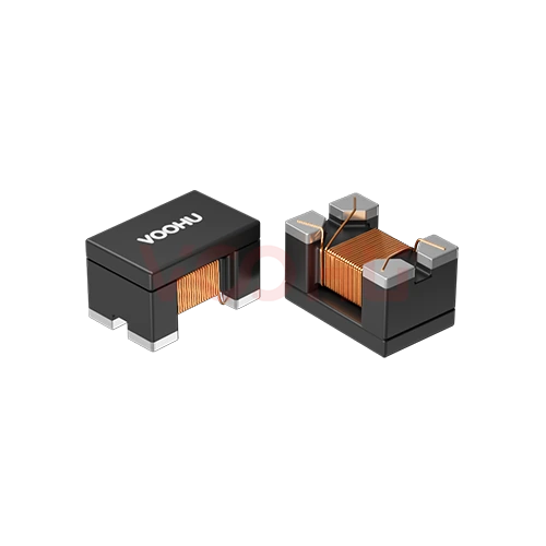 WHLC-2012A-102T0 100/1000BASE-T Cap+CMC Size2012(0805) Impedance(Ω)1000 non-PoE
> View Details
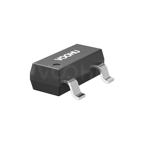 WHALD30E2B: Bidirectional ESD Protection; Withstand Voltage: 30V; Contact Discharge: ±30kV / ±30kV; PF: 0.9; Package: SOT-23.
> View Details