
Ethernet Circuit Design: How Do You Connect the PHY, Magnetics and RJ45?
Ethernet circuit design comes down to five blocks in a row: the MAC in your processor, the PHY, the LAN transformer (the magnetics), ESD and surge protection, and the RJ45 jack. Choose a PHY that matches your MAC interface and port speed. Pick magnetics rated for the same speed and number of pairs, with the isolation rating your product standard needs. Wire the PHY-side center taps as the PHY datasheet shows, terminate the cable-side center taps, route the MDI pairs as 100 Ω differential traces, keep copper out from under the magnetics, and isolate chassis ground from signal ground. An RJ45 jack with integrated magnetics (MagJack) replaces the separate transformer and jack. VOOHU supplies LAN transformers, MagJacks, RJ45 jacks and protection parts for this circuit, and distributes JL-series Ethernet PHYs.
What does an Ethernet interface circuit consist of?
Most SoCs and many microcontrollers integrate the MAC, and some integrate theEthernet PHYas well; otherwise the PHY is a separate chip that drives the MDI pairs toward the magnetics. If the port is one of several interface types on your board, our overview ofnetwork interface typesshows what other ports need.
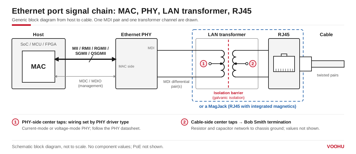
The Ethernet interface circuit: MAC, PHY, LAN transformer with its isolation barrier, and RJ45. The PHY-side center taps follow the PHY driver type; the cable-side center taps go to the termination network.
How do you connect the Ethernet PHY to the transformer and RJ45?
- MDI pairs.10BASE-T and 100BASE-TX use two pairs, on RJ45 pins 1-2 and 3-6. 1000BASE-T and faster use all four pairs. Each pair runs from the PHY to one transformer channel and on to the RJ45.
- PHY-side center taps.Whether they go to a supply or to a capacitor depends on whether the PHY has a current-mode or a voltage-mode line driver, so take the connection from the PHY datasheet. Seevoltage-mode vs current-mode PHYsandhow to connect a LAN transformer to the PHY.
- MDI termination.Some PHYs integrate the termination resistors. TheJL2101C-NIgigabit PHY, which VOOHU distributes, states in its product brief that its MDI termination resistors are integrated; it runs from a single 3.3 V supply and connects to the MAC over RGMII.
- Cable-side center taps.These usually go to a common-mode termination network. How to wire it is covered inBob Smith termination and center tap connection.
Why does Ethernet need magnetics?
IEEE 802.3 requires a twisted-pair Ethernet port to isolate the cable from the device circuits. The LAN transformer provides that isolation and blocks DC between the PHY and the cable, while its center-tapped windings pass the differential signal and reject common-mode noise. TheWHSG24701Gdatasheet, for example, lists a 1CT:1CT turns ratio, common-mode rejection of −30 dB minimum from 1 to 100 MHz, and a Hi-Pot rating of 1500 VAC, 1 mA, 60 s.
Choose the isolation rating from your product standard. Where a design needs more, some transformers are built for it: the 10/100BASE-TXWHSH16F01D4is rated 4000 VAC, 1 mA, 60 s, and its datasheet gives 7 mm clearance and 10 mm creepage, designed to IEC 60601-1 and IEC 60950-1. Why a port can still fail an isolation test is explained inwhy an Ethernet port fails the Hi-Pot test.
Discrete LAN transformer or RJ45 with magnetics?
A discreteLAN transformerlets you place the magnetics, termination and RJ45 yourself and reach every center tap. A MagJack saves board area and routing because the transformer, and often the termination, sit inside the jack. The table shows the values to check for three parts, taken from their datasheets.
| Part | Type | Key datasheet values | Center taps and termination |
|---|---|---|---|
| WHSG24701G | Discrete LAN transformer, 100/1000BASE-T, 24-pin SMD | OCL 350 µH min at 100 kHz, 0.1 V, 8 mA DC bias; insertion loss −1.1 dB max, 1–100 MHz; CMR −30 dB min, 1–100 MHz; Hi-Pot 1500 VAC, 1 mA, 60 s; 0 to +70 °C | All eight center taps brought out on separate pins (1, 4, 7, 10 and 15, 18, 21, 24) |
| WHSM24706C2 | Discrete LAN transformer, 10GBASE-T, 24-pin SMD | OCL 100 µH min at 100 kHz, 100 mV, 18 mA DC bias; insertion loss −1.2 dB max, 1–200 MHz; Hi-Pot 1500 VAC, 1 mA, 60 s; −40 to +85 °C including temperature rise | Chip side on pins 1–12, with center taps on pins 1, 4, 7 and 10; cable side on pins 13–24 |
| SYT111Q066AA2A1D | Gigabit RJ45 jack with integrated magnetics, non-PoE | OCL 350 µH min at 100 kHz, 100 mV, 8 mA DC; insertion loss −1.0 dB max, 1–100 MHz; CMR −30 dB min, 1–100 MHz; −40 to +85 °C | Cable-side termination built in: four 75 Ω resistors joined to a 1000 pF, 2 kV capacitor to pin 10 (GND) |
What are the design guidelines for an Ethernet PCB?
PHY vendors publish layout checklists, and they are the source to follow. TI'sEthernet PHY PCB Design Layout Checklist (SNLA387)gives these rules for the MDI side:
- Keep each MDI trace shorter than 2 inches (2000 mil), with as few vias and stubs as possible.
- Length-match the traces within 20 mil for 1 Gbit/s and within 50 mil for 10 and 100 Mbit/s.
- Route them as 100 Ω differential pairs with ±10% control.
- Keep same-layer ground at least 3 times the trace width away from an MDI trace, 5 times preferred.
- Separate different differential pairs by at least 30 mil.
- Keep ground continuous on the layer under the MDI traces, and void it only under components on the line, such as the magnetics, chokes, AC coupling capacitors and ESD diodes.
Should there be a ground plane under Ethernet magnetics?
No. The same TI checklist says no metal should be under the magnetics on any layer; if metal is unavoidable, it must at least be separated by a ground plane. Metal under an RJ45 jack with integrated magnetics is allowed. The cleared area also keeps copper away from the isolation gap between the two sides of the transformer.
Treat chassis ground the same way. TI recommends at least 20 mil of keep-out on all layers between earth ground and the rest of the board, with the two connected only through a capacitor and a resistor of 1 MΩ or more. The RJ45 shield connects to chassis ground.
Where do ESD and surge protection go on an Ethernet port?
TI's checklist points to its Ethernet-specific ESD note, which places the protection device on the PHY side of the magnetics rather than the connector side, because the connector side can see high common-mode voltage swings. Check that the device's clamping range suits the signal voltages in the PHY datasheet. Surge protection is covered inEthernet port surge protection design. VOOHU suppliesTVS and ESD devices, gas discharge tubesandvaristorsfor these positions.
Which VOOHU parts fit your Ethernet circuit?
- WHSG24701G: a gigabit port with discrete magnetics, when you want access to every center tap.
- SYT111Q066AA2A1D: a gigabit port in one part, with the cable-side termination already inside.
- WHSM24706C2: a 10GBASE-T port, rated −40 to +85 °C including temperature rise.
- JL2101C-NI: a gigabit PHY for an RGMII host, with integrated MDI termination.
To compare more part numbers, use theLAN transformer selector filtered to 10/100/1000BASE-Tor theRJ45 selector filtered to integrated magnetics. For complete reference designs, see theEthernet solution page.
产品WHSG24701G
产品SYT111Q066AA2A1D
方案/solution-ethernet/
FAQ
Q1: What is the differential impedance of Ethernet traces?
The MDI pairs between the PHY, the magnetics and the RJ45 are typically routed as 100 Ω differential pairs with ±10% control, as TI's Ethernet PHY layout checklist recommends. Check the PHY vendor's own layout guide as well.
Q2: How closely must Ethernet differential pairs be length-matched?
TI's checklist gives 20 mil for 1 Gbit/s and 50 mil for 10 and 100 Mbit/s for the MDI traces. Apply the length-matching on the same end of the pair, and follow your PHY datasheet if it is stricter.
Q3: How does PoE pass through the Ethernet transformer?
Power over Ethernet is applied between the center taps of the transformer windings on the cable side, so the DC current flows through the cable pairs while the data passes through the windings. The PoE controller handles power, not the PHY, and the transformer must be a PoE-rated part. See thePoE solution page.
Q4: Can Ethernet work without a transformer?
For an RJ45 port that connects to a cable, no: IEEE 802.3 requires the cable side to be isolated, and the LAN transformer provides that isolation. Transformerless, capacitor-coupled links are only used for short board-to-board connections with no cable, and you should follow the PHY vendor's application note for them.
Get help checking your Ethernet port design
Drawing an Ethernet port? Send the PHY part number, the port speed, the isolation rating you need and your schematic of the port through oursample and support form. Our FAE team can suggest a LAN transformer or MagJack that fits, and check the center-tap and termination wiring against the PHY datasheet. Samples are available for evaluation, and selected parts are free of charge. Our FAE team will be glad to confirm the options for your project. VOOHU supplies RJ45 and SFP connectors, LAN and PoE transformers, common mode chokes and Ethernet PHY and switch chips from Suzhou, China, to more than 1,500 customers.
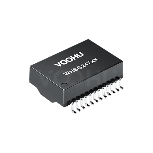 WHSG24701G Single Port SMD Gigabit Base-T PIN24 non-PoE LAN Transformer
> View Details
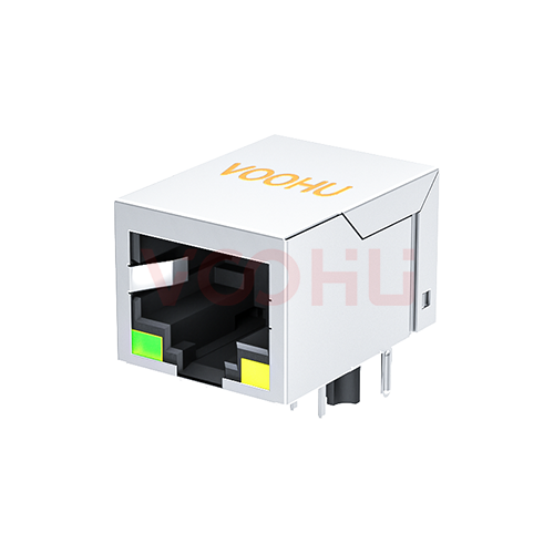 SYT111Q066AA2A1D 90° 1*1 Tab Down LED G/Y 100/1000BASE DIP RJ45
> View Details
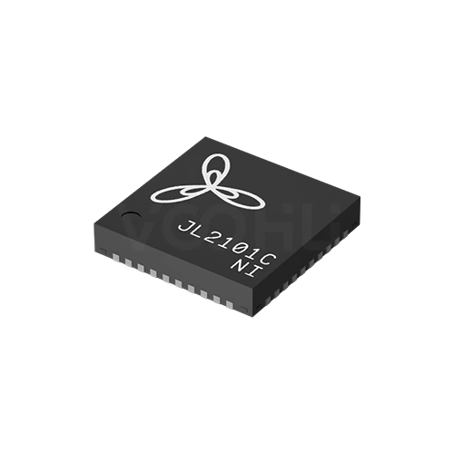 JL2101C-NI Single Port 1000M VCC:3.3V/2.5V/1.8V Industrial Grade RGMII-COP
> View Details
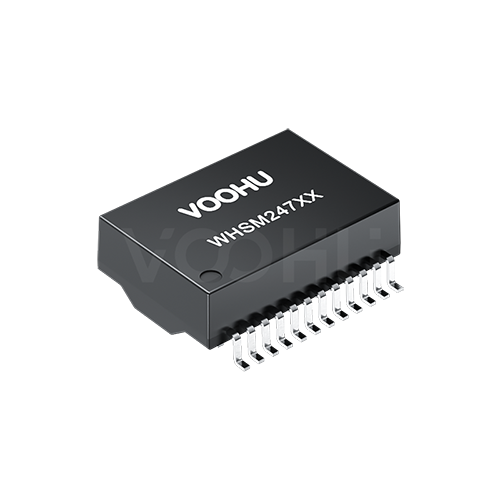 WHSM24706C2 10G Base-T Single Port 24PIN PoE++ LAN Transformer
> View Details