A CAN bus communication circuit has five blocks between the microcontroller and the cable. A CAN transceiver converts TX/RX logic into the CAN_H/CAN_L differential pair. An optional digital isolator, powered by an isolated supply, breaks ground loops. A TVS clamps ESD and surge, and a common mode choke (CMC) improves EMC. Termination closes the line.
ISO 11898-2 places a nominal 120 Ω resistor at each physical end of the bus, matching the twisted-pair cable, so a powered-down bus measures about 60 Ω between CAN_H and CAN_L. Split termination replaces each 120 Ω with two 60 Ω resistors and a capacitor to ground, adding common-mode filtering. Termination is mandatory; isolation, the TVS and the CMC depend on the environment and the EMC target.
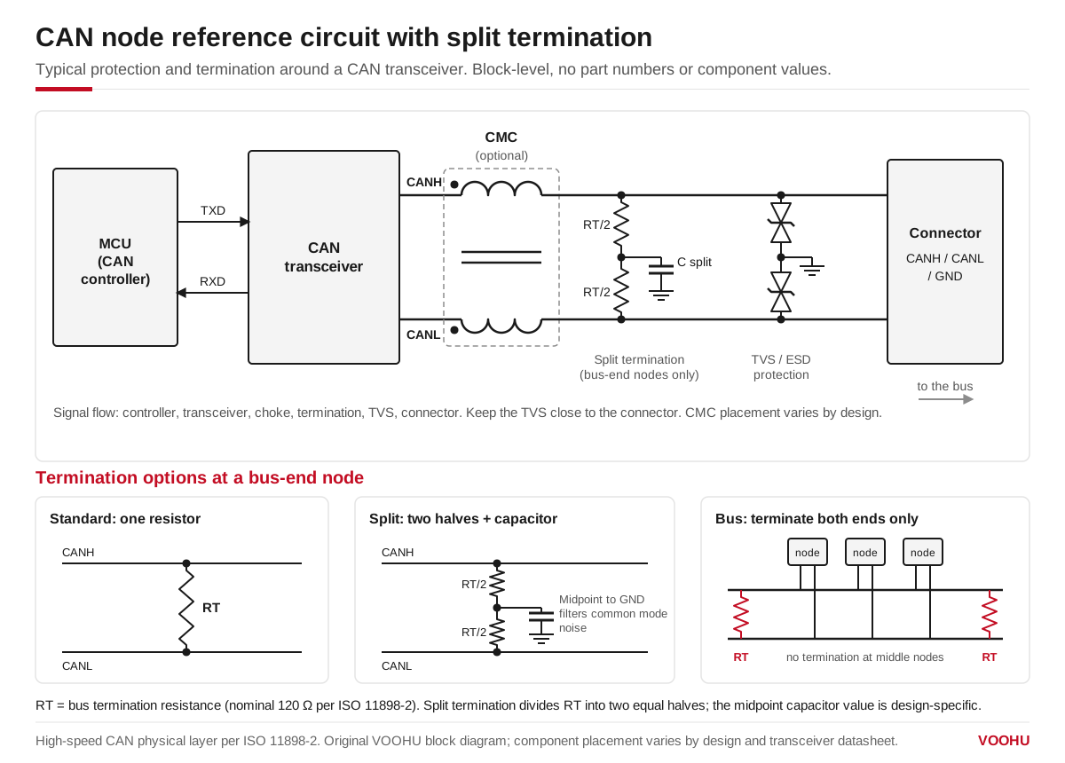
Terminate a CAN bus only at its two ends; split termination divides RT into two halves and adds a midpoint capacitor to ground to filter common mode noise.
Bosch introduced the Controller Area Network in the 1980s. Its multi-master access, non-destructive bitwise arbitration and differential signalling suit vehicles, where it links the ECU, T-BOX and body controllers, and robots with many joint-drive nodes.
#What does each block in a CAN communication circuit do?
#How does the CAN transceiver drive the bus?
The transceiver is the interface chip between the CAN controller in the MCU and the two bus wires. It shifts the single-ended TX and RX logic levels to the differential CAN_H/CAN_L pair.
In the dominant state the driver actively pulls CAN_H and CAN_L apart. In the recessive state it stops driving, and the termination resistors pull the differential voltage back towards zero. This is why the bus behaves as a wired-AND: any node sending dominant overrides every recessive node.
Arbitration, error detection and bit timing belong to the CAN protocol controller, not to the transceiver. The transceiver adds bus-pin fault protection and the noise immunity of differential signalling.
#When do you need an isolated CAN circuit?
Isolate the bus when nodes sit on different grounds, when cables are long, or when a fault on the bus must not reach the controller. A digital isolator passes TX and RX across an isolation barrier, usually by capacitive or magnetic coupling. The ground offset between nodes can then exceed the transceiver's common-mode range without corrupting data.
Many designs use an integrated isolated CAN transceiver instead. Either way, the bus side needs its own supply. A push-pull converter with an isolation transformer can generate a 5V_ISO rail dedicated to the transceiver VCC and the isolator secondary. VOOHU push-pull transformers such as the WHST06D02A0 are made for this kind of converter; check the turns ratio against your input and output voltages in the datasheet. The controller side keeps the system 3.3 V or 5 V rail.
#Where should the TVS and common mode choke go?
The TVS protects the transceiver bus pins from ESD, electrical fast transients and surge. The common arrangement is one bidirectional TVS from each line to ground, often as a dual device in one package. Place it close to the connector with short, wide traces to ground.
Choose a TVS whose standoff voltage sits above the highest voltage the bus lines can see in normal operation. Its clamping voltage must stay below what the transceiver bus pins can survive. Keep capacitance low, especially for CAN FD data rates.
A common mode choke has two windings with the same number of turns on one core. Differential current cancels in the core, so CAN signals see low impedance. Common-mode noise sees high impedance and is attenuated. This helps against motor and switching-supply noise and against radiation from the cable.
When you select a signal line CMC for CAN, weigh four points:
- Common-mode impedance in the frequency band where your noise sits
- Low DC resistance, so the choke does not eat into bus voltage margin
- Low leakage inductance, so it does not ring with the bus capacitance and distort edges
- Rated current and voltage above the bus fault conditions you design for
VOOHU signal line common mode chokes come in 2012, 3225 and 4532 sizes. For impedance, DC resistance and current ratings, see the datasheet of each part.
#CAN bus termination: 120 Ω or split termination?
A CAN bus is a transmission line. When an edge reaches an open end, it reflects and causes ringing and overshoot, which can corrupt bits. ISO 11898-2 specifies a nominal 120 Ω cable, so each end of the trunk gets a nominal 120 Ω resistor between CAN_H and CAN_L.
Terminate only the two physical ends. Nodes in the middle of the bus, and short stubs, stay unterminated. With power off, a correctly terminated bus measures about 60 Ω between CAN_H and CAN_L: two 120 Ω resistors in parallel. A reading near 120 Ω means one end is missing; about 40 Ω means one terminator too many.
Split termination divides each 120 Ω resistor into two 60 Ω resistors in series. The midpoint connects to ground through a capacitor, whose value should follow the transceiver datasheet. The capacitor gives common-mode noise a low-impedance path and steadies the recessive common-mode level. Match the two resistors closely; a mismatch converts common-mode noise into differential noise.
Check the resistor power rating against the fault cases you design for, such as a bus line shorted to the supply.
#How should the CAN interface be laid out on the PCB?
- Place the isolator and transceiver close together to keep the logic traces short.
- Route CAN_H and CAN_L from the transceiver to the connector as a symmetric, equal-length differential pair, with a differential impedance of about 120 Ω.
- Put the CMC, TVS and termination near the connector, with the TVS ground return short and wide.
- Keep the controller ground (GND) and bus-side ground (GND_ISO) fully separate across the barrier.
- A common practice is to connect GND_ISO to chassis or protective earth through a high-value resistor in parallel with a high-voltage capacitor, for example 1 MΩ and 10 nF. This bleeds static charge and gives high-frequency noise a return path without closing a ground loop.
#Frequently asked questions
Do I need a 120 Ω termination resistor at every CAN node?
No. Fit a nominal 120 Ω resistor only at the two physical ends of the bus, between CAN_H and CAN_L. Middle nodes stay unterminated. With power off, measure about 60 Ω between CAN_H and CAN_L; 120 Ω means a terminator is missing.
Is split termination better than a single 120 Ω resistor?
For EMC, usually yes. Two 60 Ω resistors with a capacitor from the midpoint to ground filter common-mode noise and steady the recessive level. Use matched resistors and take the capacitor value from your transceiver datasheet.
Does a CAN bus need a common mode choke?
Not always. A CMC helps when the node must pass radiated emission or immunity tests, or runs near motors and inverters. Choose one with low DC resistance and low leakage inductance so it does not distort CAN edges.
Need a quote, samples or selection support?
Part number WHST06D02A0 is filled in for you. Add the quantity and lead time and submit. Our FAE team will be glad to confirm the options for your project.
Before you order: samples, MOQ, lead time and import duties in our ordering guide →