Shielded vs Unshielded Power Inductor: When Do You Need a Shielded Inductor?
A shielded power inductor surrounds its winding with magnetic material, such as a drum core inside a ferrite sleeve, so most of its magnetic field returns through the core. An unshielded inductor leaves more of its field in the air around it, where it can couple into nearby traces, components and other inductors; a semi-shielded part sits in between. Molded inductors, with the winding embedded in a magnetic powder core, are a separate construction with their own field behaviour. Use a shielded inductor when the inductor is close to RF, clock, audio, sensor or high-impedance analog circuits, next to other magnetics or an Ethernet port, on a dense board, or when radiated emission margins are tight. Where there is room around the part, an unshielded inductor is often a sound, lower-cost choice. VOOHU's FAE team can review the placement of a VOOHU power inductor on your layout.
What is a shielded inductor?
In a shielded inductor, magnetic material closes the flux path around the winding, so the field returns through the core instead of through the air around the part. A common construction is a drum core inside a ferrite sleeve. A semi-shielded inductor keeps the open drum core but coats the winding with a magnetic resin. A molded inductor is built differently: the winding is embedded in the magnetic powder that forms the core.
"Shielded" describes the construction, not a measured level. There is no common standard for how much field a shielded part may leak, and manufacturers apply the label differently, which is why engineers sometimes ask how a given part counts as shielded at all.
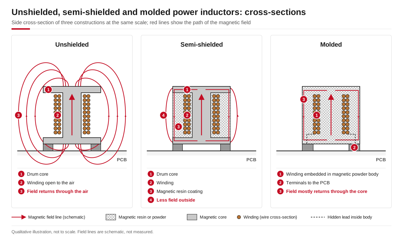
Unshielded, semi-shielded and molded constructions, and the paths their magnetic field takes. Illustration only, not measured.
What are the differences between a shielded and non-shielded inductor?
| Check | Unshielded | Semi-shielded | Shielded (ferrite sleeve) | Molded |
|---|---|---|---|---|
| Construction | Winding on a drum or bobbin core, open to the air | Drum core with a magnetic resin coating over the winding | Drum core inside a ferrite sleeve that encloses the winding | Winding embedded in a magnetic powder core |
| Field outside the part | Most | Less | Least of the drum-core types | Low; depends on the design |
| Sensitivity to placement and orientation | Highest | Medium | Lowest of the drum-core types | Depends on the design; ask the manufacturer |
| Often chosen for | Lower cost, and often more inductance or saturation current for a given size | A balance of size, cost and stray field | Dense layouts, nearby sensitive circuits, tight emission margins | Surface-mount power rails that need high current in a small body |
Shielding by itself does not set the current ratings. Compare saturation and rated current on each datasheet; seeinductor saturation current vs rated current.
When do you need a shielded inductor?
- Near RF circuits and antennas.The switching frequency and its harmonics can couple into receivers.
- Near clocks, audio inputs, sensors and high-impedance analog nodes.A changing magnetic field induces voltage in any loop it passes through.
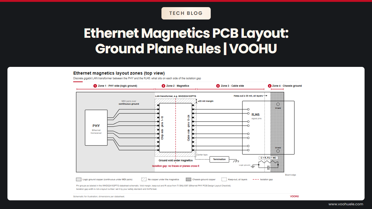
- Near Ethernet magnetics, RJ45 jacks and cable connectors.Noise coupled there can leave the board on the cable.
- With several inductors close together.Unshielded parts placed side by side can couple to each other.
- When radiated emission results are close to the limit.
An unshielded inductor with clear space around it, away from sensitive circuits, is often fine. The choice is about the field near the part, not about the quality of the part.
Molded vs shielded inductor: what is the difference?
"Molded" names how a part is made: the winding is embedded in the magnetic powder that forms the core. "Shielded" names what a construction is meant to do: keep more of the field inside the core. One describes the process, the other the intended effect, and neither is a measured grade.
How much field remains outside any part depends on its design, in either construction; none makes it zero. If your layout is critical, read the construction on the datasheet and ask the manufacturer's FAE team to check it for your placement.
How do you tell how well an inductor is shielded?
- The construction and structure drawing.A drum core alone, a resin coating, a sleeve or a molded body; and whether core material covers the top and sides of the winding.
- Labels.Shielded and semi-shielded are not standardized grades, so read the construction rather than the label.
- Field data.Ask the manufacturer whether it has near-field measurements for the part.
- Your own board.Scan the inductor and nearby traces with a near-field probe, and check the product's emission results.
Each VOOHU datasheet describes the construction of its series, and our FAE team can tell you what it means for your layout.
How do I choose the correct inductor type and package for a buck converter?
Start with inductance and the two current ratings, then size and height, then the construction for the field around the part. VOOHU's power inductors are molded types (WHYT, WHYTA and WHYTP series) and power bead inductors (WHPBU). Their datasheets describe the construction in their own words:
| Series | Construction stated on the datasheet | Size (mm) | Inductance | DCR max | Isat typ | Irms typ |
|---|---|---|---|---|---|---|
| WHYTP0320 | "Wire Wound Molded SMD Power Inductors"; carbonyl powder core | 3.4 × 3.2 × 1.8 | 0.33–10 µH | 21–422 mΩ | 10–1.6 A | 8–1.4 A |
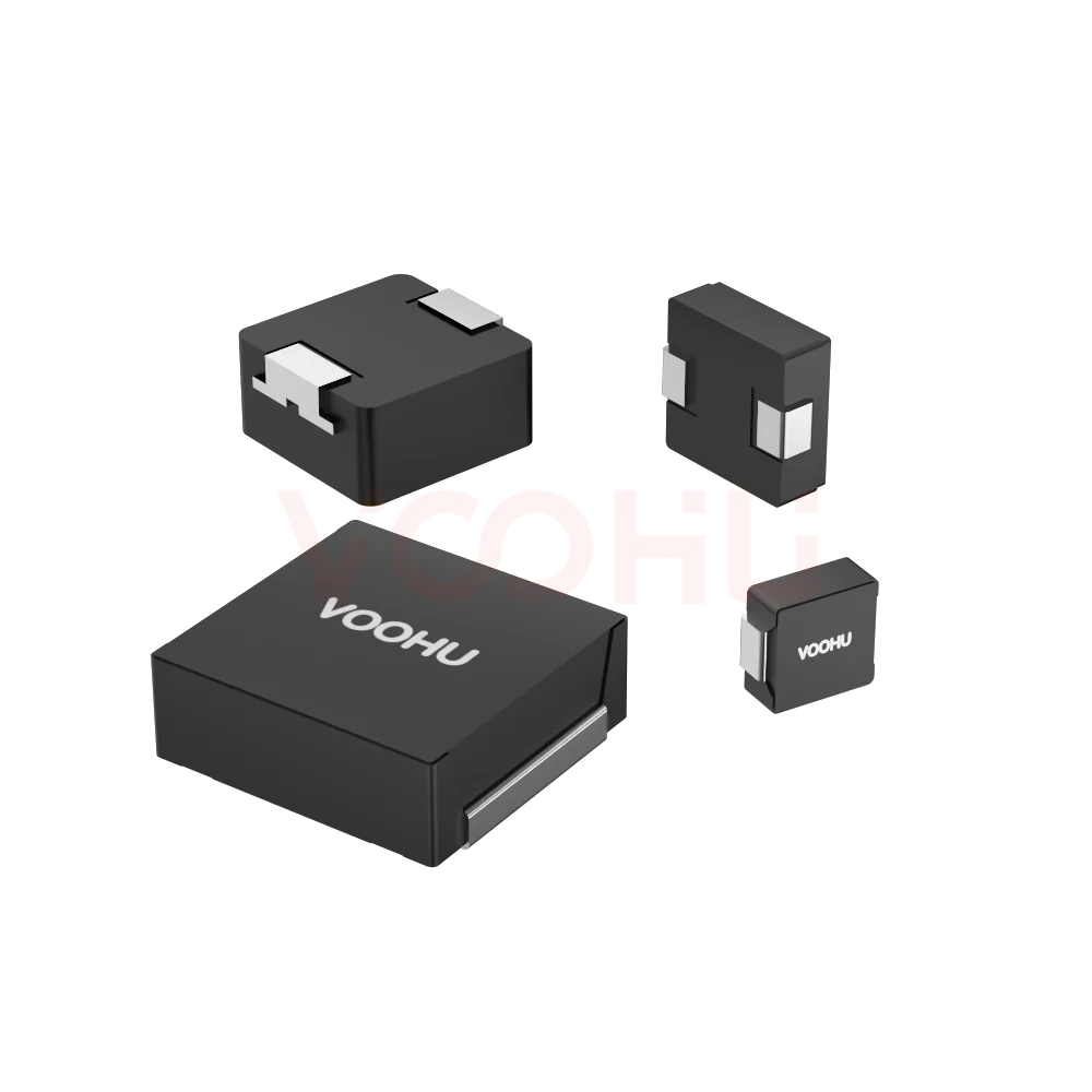
| WHYTA0420 | "Ultra low buzz noise due to molding construction" | 4.4 × 4.2 × 1.8 | 0.1–10 µH | 4–282 mΩ | 22–2 A | 13–1.6 A |
| WHYT1250 | "Ultra low buzz noise due to molding construction"; alloy powder core | 13.45 × 12.6 × 4.8 | 0.22–47 µH | 0.7–130 mΩ | 75–5.0 A | 50–3.0 A |
| WHPBU-100710N | "Closed magnetic circuit design reduces leakage flux" | See the series datasheet | 100–470 nH | See the series datasheet | 117–20 A at 25 °C | 70 A heating current |
Isat is defined at about a 30 % inductance drop on the molded series and about 20 % on the WHPBU-100710N, and Irms at about a 40 °C rise on all four, so compare the two families on those terms. Good starting points are theWHYTP0320-1R0M(1.0 µH, 38 mΩ max, Isat 5 A and Irms 4 A typical) where board area is tight, theWHYTA0420-1R0M(1.0 µH, 27 mΩ max, Isat 7 A and Irms 6 A typical), theWHYT1250-1R0M(1.0 µH, 2.2 mΩ max, Isat 35 A and Irms 26 A typical) for high-current rails and theWHPBU-100710N-R22L0(220 nH, Isat 60 A typical at 25 °C, heating current 70 A typical). Filter themolded power inductor selectorby series, or browse theWHYTA, WHYTPandpower bead inductorranges. Related reading:molded power inductor selection and layoutandhow to stop molded power inductor coil whine.
If the inductor will sit next to RF, sensor or Ethernet circuits, send us the layout, and our FAE team can confirm whether the construction suits that placement.
产品WHPBU-100710N-R22L0
FAQ
Q1: Does a shielded inductor store less energy than an unshielded one?
Not for the same inductance and current: the stored energy is ½LI² either way. Shielding changes where the field sits, not that formula. What can differ is the combination of inductance, saturation current and size a manufacturer offers in each construction, so compare the datasheet values of the parts you are considering.
Q2: How do you shield an inductor?
Choose a shielded construction first. If an unshielded part stays, keep sensitive traces and loops away from it and out from under it, and give neighbouring inductors space; spacing and orientation both change how much they couple. A metal shield can over the circuit is the last resort.
Q3: Do you need a keep-out area underneath a power inductor?
For sensitive or high-impedance signals, yes: route them away from the area under any power inductor, shielded or not, because some field remains close to the body. For the power traces and ground plane, follow the converter IC's layout guide.
Ask us to check the inductor placement on your board
Send us the layout around the inductor, the converter's switching frequency and current, and what sits nearby in thesample and support request form. Our FAE team can confirm whether the construction of a VOOHU power inductor suits that placement, suggest parts by size, inductance and current, and check the footprint. Samples are available for evaluation, and selected parts are free of charge. Our FAE team will be glad to confirm the options for your project.
VOOHU supplies RJ45 and SFP connectors, LAN and PoE transformers and common mode chokes from Suzhou, China, to more than 1,500 customers.
 WHYTA0420 series Inductance Value 0.1-10uH DCR 4-282mΩ IRMS 1.6-13A ISAT 2-22A Integrated Molded inductor
> View Details
WHYT1250 series Inductance Value 0.22-47uH DCR 0.7-130mΩ IRMS 3-50A ISAT 5-75A Integrated Molded inductor
> View Details
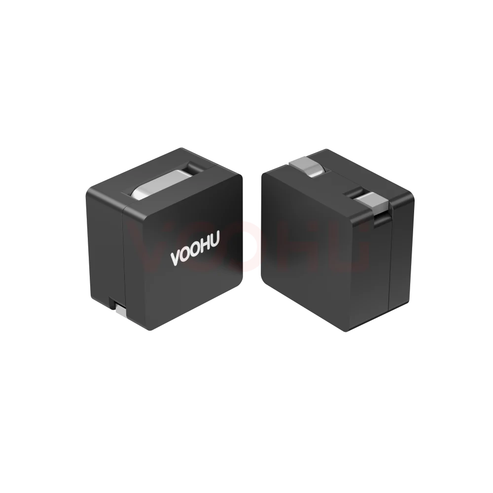 WHPBU-100710N-R22L0 Initial Inductance:220nH Tolerance: 15 (±%) DCR0.18 ± 10%mΩ Heating Current (Amps) (typ)70 Combined Inductor
> View Details
WHYTP0320 series Inductance Value 0.33-10uH DCR 21-422mΩ IRMS 1.4-8A ISAT 1.6-10A Integrated Molded inductor
> View Details