VOOHU actual combat: The network port cannot pass the Hi-Pot voltage and the leakage current exceeds the standard? Ethernet transformer isolation withstand voltage (1.5kV/3kV/4kV) and safety selection and pitfall avoidance guide
VOOHU actual combat: The network port cannot pass the Hi-Pot voltage and the leakage current exceeds the standard? Ethernet transformer isolation withstand voltage (1.5kV/3kV/4kV) and safety selection and pitfall avoidance guide
Introduction: Passed all functions and EMC, but got stuck at the last voltage level.
Almost every board with an RJ45 network port must pass a "dielectric strength (Hi-Pot) withstand voltage test" before mass production. The scenario that engineers are most afraid of is: after the functions are adjusted, the EMC is passed, and the surge is withstood, as soon as the electrodes on the production line are pressurized, the network port sparks, a leakage current alarm occurs, and the entire batch of boards is stuck at the last level. Another high-frequency confusion is: the data sheet says there are several voltage levels of 1500Vrms, 2250VDC, 3000Vrms, and 4000Vrms at the same time. Which one should I choose? If you choose a high one, you are afraid of being expensive and affecting the signal; if you choose a low one, you are afraid of failing the certification and causing reliability risks. This article starts from the isolation nature of Ethernet transformers, dismantles the real causes of Hi-Pot ignition and excessive leakage current, and combines the isolation withstand voltage (Vt) level of VOOHU full-rate network transformers to provide a set of selection methods that can be directly implemented.
1. Why must Ethernet ports be "isolated"? What does isolation withstand voltage prevent?
The core passive component of the Ethernet port is the network transformer (LAN Transformer). It uses two sets of primary and secondary windings for magnetic coupling to completely electrically disconnect the PHY side circuit from the network cable (MDI) side - there is no DC connection and differential signals are transmitted. This is "isolation". Only by understanding what it is protecting against can you choose the right voltage level.
1.1 The first thing to prevent in isolation: ground potential difference and ground circulation
Two networked devices are each connected to a different ground, and there may be a potential difference between the ground and the ground from several volts to hundreds of volts. If the network port is not isolated, this potential difference will cause ground circulation along the network cable, which may cause bit errors and packet loss, or even burn the PHY. The transformer disconnects the DC at both ends and allows only differential signals to pass through, fundamentally cutting off the ground circulation path. Isolation withstand voltage measures how high the cross-connect voltage this "wall" can withstand without breakdown.
1.2 The second thing to prevent in isolation: DC bias of PoE
In PoE applications, a DC bus voltage of up to about 57V is superimposed on the network cable, and a considerable supply current flows (from about 350mA for 802.3af to 1A for 802.3bt Type4). On the one hand, the network transformer must introduce this DC voltage at the center tap without saturation; on the other hand, its winding insulation must withstand this DC voltage for a long time without deteriorating. This is why when selecting a PoE port, in addition to looking at the withstand voltage, you also need to look at the "PoE current" level of the transformer - VOOHU Gigabit Network Transformer provides multi-level capabilities from non-PoE to 4PPoE 3000mA.
1.3 The third thing to guard against during isolation: Lightning surge and “safe” isolation
The network ports of outdoor security, power, and industrial equipment are hung on long cables, and lightning-induced surges can reach kV levels. The isolation barrier is the last wall between the "signal side" and the "shell/earth" when a surge hits. Two concepts that are often confused must be distinguished here: functional isolation (to ensure the normal operation of the circuit and suppress common mode) and safety isolation (to prevent dangerous voltages from endangering people). The vast majority of Ethernet ports belong to SELV low-voltage systems and only require functional/basic isolation; only when the port may be in contact with mains power or used in special occasions such as medical treatment, "reinforced insulation" is required, and the voltage withstand requirements will suddenly increase.
2. Why does Hi-Pot catch fire? Why does the leakage current exceed the standard?
2.1 First understand what Hi-Pot is measuring
The dielectric strength test (Dielectric Withstand / Hi-Pot) is to apply a test voltage much higher than the operating voltage between the "signal side" and the "casing/earth" for a period of time to see whether the insulation will break down and whether the leakage current will exceed the standard. The basic requirements of IEEE 802.3 for Ethernet port MDI are 1500Vrms, 50/60Hz, and duration of 60 seconds. The test can be done with alternating current (AC) or equivalent direct current (DC): according to the peak equivalent value, 1500Vrms is approximately 1500×1.414≈2121V, and 2250VDC is often used in engineering. For the sake of efficiency, production lines often use a shorter time (1~2 seconds) plus ramp boost instead of 60 seconds.
2.2 Three "hidden sources" of leakage current
Leakage current is not entirely due to poor insulation, but more of a "capacitive" current. The first source is the inter-turn capacitance of the network transformer (distributed capacitance Cw between the primary and secondary windings) - the higher the withstand voltage and the larger the winding spacing, the smaller this capacitance is; the second source is when the port is Bob Smith terminated, the center tap is connected to the capacitor of the shell through a 75Ω resistor. It directly spans the isolation barrier, and the test voltage is almost full across it; the third source is the Y capacitance from everywhere in the circuit to the shell/earth. When doing AC Hi-Pot, these capacitors will flow a capacitive current of I=2πfCV. If the capacitance value is too large, it will be mistakenly judged as "exceeding leakage current". Switching to DC Hi-Pot can avoid most capacitive currents, which is also the fundamental reason why many production lines switch to DC withstand voltage.
2.3 The real culprit of “sparking”: capacitor withstand voltage and PCB creepage distance
The real "ignition" is often not found in the transformer itself, but in two places that are easily overlooked. One is that the voltage resistance of the center tap capacitor is low: this Bob Smith capacitor spans between the signal and the casing. It has to withstand 1500Vrms or even 2250VDC alone during testing. If only a small capacitor of 500V or 1kV is used, it will inevitably be broken down. The industry practice is to choose Y capacitors or special high-voltage ceramic capacitors with a voltage of 2kV and above. The second is that the PCB creepage distance (Creepage) and electrical clearance (Clearance) are insufficient: a sufficiently wide "isolation trench" (moat) must be dug between the primary and secondary pins of the transformer, between the network port area and the internal ground, and sufficient spacing between the RJ45 shell, shielding layer and signal traces must be ensured, otherwise high voltage will creep up and discharge along the board surface or in the air. Based on experience, 1500Vrms is basically isolated under ordinary pollution levels, and the isolation distance is generally not less than 1.6mm; if it is above 3000V, the creepage meter must be further increased according to safety regulations.
3. How to choose the isolation withstand voltage level? Combined with VOOHU network transformer to provide solutions
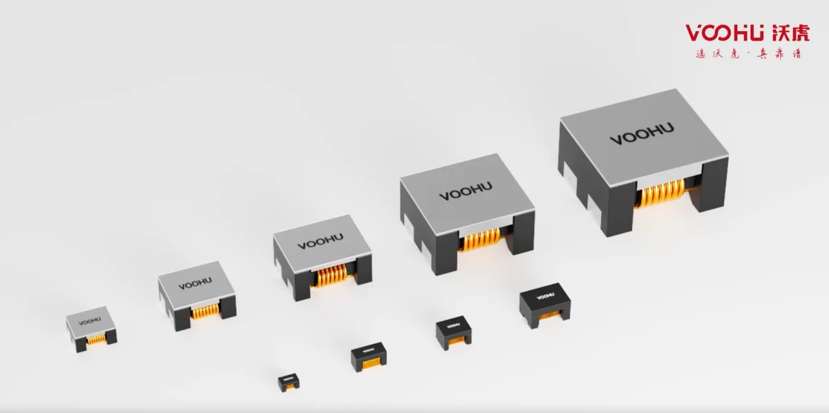
The core principle of selection is: first determine "how high the isolation level is required" according to the application environment, then leave enough surge and safety margins, and finally match the network transformer, integrated magnetic RJ45, center-tap capacitor, protective device and PCB spacing as a whole. VOOHU's100/1000 BASE-T Ethernet TransformerProvides 1500 / 2000 / 2500 / 3000 / 4000 / 4500 / 4800 / 5000 Vrms multi-level isolation voltage (Vt), single-port WHSG and dual-port WHDG series; available in 100M scenarios with large shipments10/100 BASE-TX Network Transformer;Multi-rate uplink has2.5G/5G BASE-T network transformation(WHSQ/WHDQ series) etc. If you want to save board space and simplify termination, you can directly chooseIntegrated magnetic RJ45(SYT series, including "+ lightning protection" integrated protection version). When lightning strike certification is required, add another level.GDT gas discharge tube(WHGD090/200/400V) for rough protection, equipped withTwo-way TVSMake fine clamps. The following table gives the correspondence between common scenarios and isolation voltage levels:
| Application Scenario/Isolation Level | Recommended isolation voltage Vt | VOOHU recommended series | Center tap capacitor withstand voltage | Key takeaways |
|---|---|---|---|---|
| Indoor consumption/desktop (functional isolation, 802.3 basic requirements) | 1500Vrms/60s (≈2250VDC) | Gigabit WHSG/WHDG; 100M 10/100 network change | ≥2kV | Cost-optimized and meets IEEE 802.3 |
| PoE power supply / industrial strong interference / long cable | 2000–3000Vrms | High voltage gear WHSG24R03D0; integrated SYT | 2kV | Leave common mode and bias margins, and pay attention to the PoE current profile |
| Outdoor Security/Electricity/Lightning Strike Certification Required | 3000–4000Vrms + coarse protection | Integrated SYT (+ lightning protection) + WHGD 200/400V | ≥2kV | GDT rough protection + TVS fine clamping two-level cooperation |
| Close to mains/medical, etc. Reinforced insulation | 4000–5000Vrms (customized) | Customized reinforced insulation network transformer | ≥3kV | Evaluated according to safety regulations IEC 62368/60601 |
| Multi-rate 2.5G/5G/10G uplink | 1500–3000Vrms | 2.5G/5G WHSQ/WHDQ; 10G WHSM | 2kV | Taking into account both voltage resistance and insertion loss/return loss |
Special reminder: When the port is connected to the GDT of the shell, if the test voltage of the DC Hi-Pot of the production line is higher than the DC breakdown voltage of the GDT (such as the 90V level), the GDT will discharge before the insulation, resulting in a misjudgment of "exceeding the leakage current". The countermeasure is to select the GDT above the test voltage according to the surge level (for example, 200V/400V WHGD for outdoor 6kV surge), or bypass the GDT end during the voltage withstand process before testing again.
Conclusion: A solid foundation for "isolation" is the reliable foundation for the network port.
The isolation voltage of the Ethernet port is not "the higher, the better", but "enough with margin". For most indoor consumer and commercial equipment, it is sufficient to follow IEEE 802.3's 1500Vrms functional isolation, which is the most cost-effective; for PoE, industrial, long cable and outdoor scenarios, the isolation withstand voltage should be raised to 2000~3000Vrms and equipped with coarse and fine two-level protection; only in special occasions such as close to mains power or medical care, reinforced insulation above 4000Vrms is required. By treating the Vt level of the network transformer, the center tap capacitor withstand voltage (≥2kV), the PCB creepage distance and the protective devices as a system, the network port can be Hi-Potted in one go and be stable and reliable in the long term. VOOHU provides full-range network transformers and integrated magnetic RJ45 from 1500V to 5000V, and supports customized reinforced insulation solutions according to certification requirements, helping engineers to make the final hurdle of "isolation" solid and reliable.
Frequently Asked Questions (FAQ)
Q1. Is 1500Vrms enough for the isolation voltage of the Ethernet port?
A: For ordinary network ports in indoor and SELV environments, 1500Vrms/60s is the basic requirement of IEEE 802.3, which is completely sufficient and the most economical. However, for PoE power supply, industrial strong interference, long cables or outdoor ports, it is recommended to increase the voltage to 2000~3000Vrms to leave surge and common mode margin; only if it is likely to come into contact with mains power or be used for medical patients, reinforced insulation above 4000Vrms is required.
Q2. What are the most common reasons why Hi-Pot sparks and causes leakage current alarms when pressurized?
A: Ninety percent of the problem is not with the transformer itself, but with the capacitor across the isolation barrier at the center tap (Bob Smith). The withstand voltage is low, or the creepage distance from the primary and secondary sides on the PCB and the signal to the shell is not enough. First replace the capacitor with a withstand voltage of 2kV or above, and then check whether the isolation trench width is ≥1.6mm. Most sparking problems can be solved.
Q3. Does the production line Hi-Pot use AC or DC? How to determine the voltage and time?
A: The standard requirements are 1500Vrms, 50/60Hz, 60 seconds. To improve the efficiency of production lines, the equivalent DC voltage is often about 2250VDC, and the voltage is ramped up in 1 to 2 seconds. The advantage of DC is that it can avoid misjudgment of capacitive leakage current; if you insist on using AC, be sure to include the capacitance between turns of the transformer and the capacitive current of Y capacitors everywhere into the leakage current threshold.
Q4. Why can’t Hi-Pot pass the GDT on the board?
A: Because the GDT directly spans between the signal and the housing. If the Hi-Pot test voltage is higher than the DC breakdown voltage of the GDT (for example, 90V level), the GDT will discharge first and the leakage current will be judged to be excessive. The countermeasure is to select the GDT above the test voltage according to the surge level (such as 200V/400V WHGD), or temporarily bypass the GDT during the voltage withstand process and then test again.
Q5. Does PoE power supply have additional requirements for the isolation voltage of the network transformer?
A: The isolation withstand voltage level itself is still determined by the environment (mostly 1500~3000Vrms), but PoE allows the winding to withstand up to about 57V DC for a long time and flow a large current, so you must pay attention to both the "PoE current" gear and the DC bias capability of the transformer. VOOHU Gigabit network converter provides multiple grades from non-PoE to 4PPoE 3000mA. For Type4 high-power PD, it is recommended to choose the 1200~1500mA grade to leave a margin.
Q6. Is there any difference in isolation capabilities between integrated magnetic RJ45 and discrete network transformers?
A: The isolation principle is the same. Integrated magnetic RJ45 (such as SYT series) seals network transformers, termination resistors, capacitors and even lightning protection devices into the connector. The isolation withstand voltage can also reach 1500~3000Vrms, which can also save board space and reduce EMC risks; the discrete solution (WHSG/WHDG) is more flexible in terms of voltage range, maintenance and replacement, and high-speed return loss fine-tuning. Just decide based on space and cost.
Q7. How many V should I choose for the withstand voltage of the center tap (Bob Smith) capacitor?
A: This capacitor spans between the signal and the casing. It has to withstand the entire Hi-Pot test voltage on its own, so the withstand voltage must be higher than the peak value of the test voltage. For 1500Vrms (peak value ≈ 2121V) test, 2kV is the lower limit, and leaving a margin is more stable. If the voltage is 3000Vrms, a dedicated high-voltage capacitor of 3kV or above should be installed. Do not use ordinary 0402/0603 small capacitors.