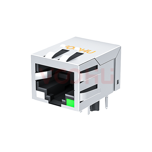
WHDG96502PTG Quad Ports DIP Gigabit Base-T PIN96 PoE:720 mA LAN Transformer


Request a Quote
Leave your details and we will send a tailored volume quote.
Our sales team will contact you within 1 business day.
Contact Sales
Reach our sales team for pricing and lead time.

Submitted
We have received your request. Our sales team will contact you within 1 business day.



For technical assistance, pleaseclick the button below to add customer service or visit the sample request pageto fill out the form. We will serve you as soon as possible.
Technical Support Email: fae.thorne@voohu.cn Phone: +86 400-1048-018
For more details, please visit theDownload Centerto get documents or click the button below to add customer service. We will serve you as soon as possible.


For purchases and small-volume orders, please contact our sales team. We support VAT general/special invoices with a convenient and efficient process.
For technical assistance or sample requests, pleaseclick the button belowto add customer service orvisit the sample request pageto fill out the form. We will serve you as soon as possible.
Customer Service Email: song.lei@voohu.cn Phone: +86 180 2130 1120
Because open-circuit inductance is measured under a DC bias, and the figure only means something if the bias is close to the real supply operating point.
The WHDG96502PTG states 350 µH Min at 21 mA bias, while the non-PoE parts in the same family state the same figure at 8 mA. When comparing PoE parts, read the bias condition alongside the inductance — comparing the numbers alone compares two different operating conditions. Bias conditions vary across the100/1000 BASE-T range.
Published electrical ratings, package dimensions, pin numbering and PoE rating all match; the difference is on the schematic — the common-mode choke on each channel is drawn with three windings on the WHDG96502PTG and two on theWHDG96504PTG.
Both assign pins 1–48 to the chip side. Where the design has specific requirements on the common-mode path, tell us the target PHY and EMC approach rather than picking from the parameter table alone.
Pins 1–48 are the chip side and pins 49–96 the cable side, labelled group by group on the drawing; the common-mode choke sits on the chip side and the transformer on the cable side.
One thing to watch: theWHDG96503PTGshares the package and the pin numbering of the WHDG96502PTG but its drawing labels the two sides the other way round. The parts cannot be placed in the same orientation, and any change between them needs the orientation re-checked against each drawing.