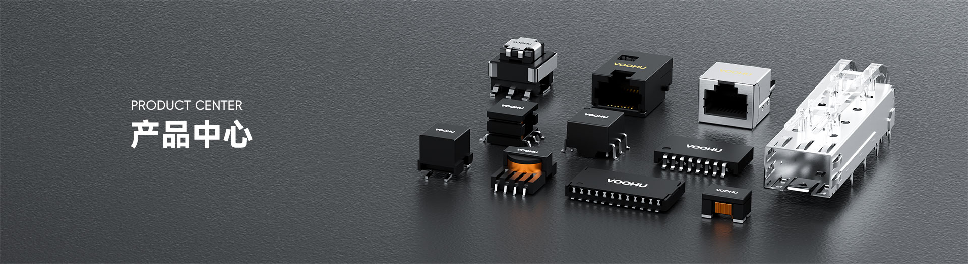
WHSG24Z01C0 100/1000Base-T Single Ports 24PIN 4PPOE(up to 3000mA) LAN Transformer
WHSG24Z01C0 100/1000Base-T Single Ports 24PIN 4PPOE(up to 3000mA) LAN Transformer





Request a Quote
Leave your details and we will send a tailored volume quote.
Our sales team will contact you within 1 business day.
Contact Sales
Reach our sales team for pricing and lead time.

Submitted
We have received your request. Our sales team will contact you within 1 business day.



For technical assistance, pleaseclick the button below to add customer service or visit the sample request pageto fill out the form. We will serve you as soon as possible.
Technical Support Email: fae.thorne@voohu.cn Phone: +86 400-1048-018
For more details, please visit theDownload Centerto get documents or click the button below to add customer service. We will serve you as soon as possible.





For purchases and small-volume orders, please contact our sales team. We support VAT general/special invoices with a convenient and efficient process.
For technical assistance or sample requests, pleaseclick the button belowto add customer service orvisit the sample request pageto fill out the form. We will serve you as soon as possible.
Customer Service Email: song.lei@voohu.cn Phone: +86 180 2130 1120
Each magnetic channel supports 1.5 A of DC balance current, and the two channels of the single port together support 3.0 A – the highest current capability among the single-port parts in this range.The 3.0 A figure is the port total with all channels working together; it is not the rating of any individual coil, and it is not 1.5 A multiplied by the coil count. Match the WHSG24Z01C0 to your target PSE/PD scheme against the actual current draw.
Size four balanced paths at 1.5 A each rather than widening one path to 3.0 A.On the WHSG24Z01C0 the cable-side centre taps are MCT1 to MCT4 at pins 24, 21, 18 and 15, and the chip-side taps are TCT1 to TCT4 at pins 1, 4, 7 and 10. Concentrating the port total into one or two traces pushes the real current density well past the design intent. The +85 °C ceiling also already includes self-heating, so the copper and thermal design have to keep ambient plus self-heating within that boundary.
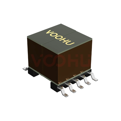
The pitch matches, the envelope does not: the WHSG24Z01C0 body is 19.90 mm × 13.00 mm with an 8.80 mm maximum height, noticeably larger than a conventional 24-pin Gigabit part.What it buys is 1.5 A per channel and 3.0 A full-channel current capability; what it costs is board area and height clearance. It cannot be placed on the basis of "also 24-pin, also 1.27 mm", and on low-profile products the 8.80 mm clearance has to be confirmed first. Other options are in the10/100/1000 BASE-T range.