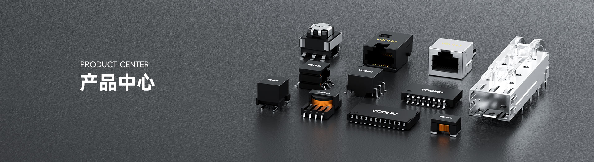
WHS16116G SMD à port unique (faible hauteur) 10/100Base - TX PIN16 non - Transformateur LAN PoE
WHS16116G Single Port SMD(Low height) 10/100Base-TX PIN16 non-PoE LAN Transformer





Request a Quote
Leave your details and we will send a tailored volume quote.
Our sales team will contact you within 1 business day.
Contact Sales
Reach our sales team for pricing and lead time.

Submitted
We have received your request. Our sales team will contact you within 1 business day.


Pour une assistance technique, veuillezcliquez sur le bouton ci-dessous pour ajouter le service client or visitez la page de demande d'échantillonpour remplir le formulaire. Nous vous servirons dans les plus brefs délais.
E-mail du support technique : fae.thorne@voohu.cn Téléphone : +86 400-1048-018
Pour plus de détails, veuillez visiter leCentre de téléchargementpour obtenir des documents ou cliquez sur le bouton ci-dessous pour ajouter le service client. Nous vous servirons dans les plus brefs délais.





Pour les commandes de petits-volumes, vous pouvez passer des commandes directement surBoutique VOOHU. Nous prenons en charge les factures TVA générales/spéciales avec un processus pratique et efficace.
Pour une assistance technique ou des demandes d’échantillons, veuillezcliquez sur le bouton ci-dessouspour ajouter un service client ouvisitez la page de demande d'échantillonpour remplir le formulaire. Nous vous servirons dans les plus brefs délais.
Email du service client : song.lei@voohu.cn Téléphone : +86 180 2130 1120
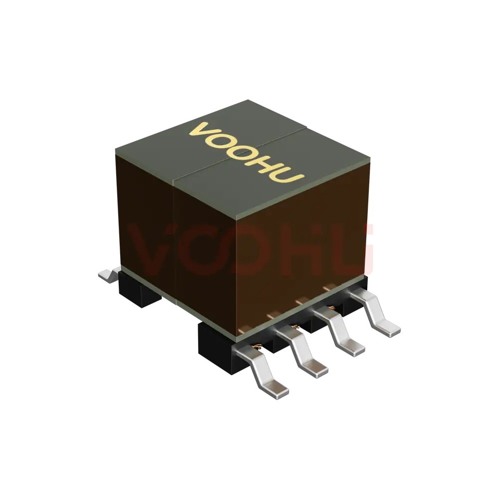
Two termination counts on one low-profile outline: both are 12.70 × 7.10 mm and 2.50 mm Max high, 9.50 mm across the leads, on 1.27 mm pitch with an 8.89 mm span — but the WHS16116G has sixteen terminations against twelve on theWHS16105G.
The internal order differs too: the WHS16116G puts the common-mode choke on the cable side, the WHS16105G on the chip side. The land patterns are not interchangeable, and the shared outline makes it easy to assume otherwise — build them as separate library entries by termination count.
Not in the published electrical ratings — the low profile does not cost insertion loss, return loss or isolation.
The WHS16116G stands 2.50 mm Max against 5.65 mm ±0.50 mm for the standard-height parts, and both hold the same two 1CT:1CT units per port. What differs is the range of specifications available: thestandard-height groupoffers a 2500 VAC high-isolation part and the low-profile group currently does not. Wide temperature is available at both heights — the low-profileWH16603T1is rated -40 °C to +105 °C. So check the temperature and isolation requirement first, then whether that height fits.
Two 1CT:1CT units, forming the two channels — one pairset — of a single 100M port, with the common-mode choke on the cable side.
The signal enters the WHS16116G from the chip side, passes the transformer first and the choke second, then reaches the cable side. That order shapes the common-mode path, so even where outline and termination count match, a change to a part with the choke on the chip side calls for EMC to be re-verified on the finished unit — the parameter table does not show this difference. Other arrangements sit in the10/100 BASE-T range.