How to Choose an SFP Cage Light Pipe: Panel Matching for No-Light, 1×4 Light-Pipe, and 2×6 Outer-Dual-Light Designs | VOOHU
How to Choose an SFP Cage Light Pipe: Panel Matching for No-Light, 1×4 Light-Pipe, and 2×6 Outer-Dual-Light Designs | VOOHU
Choosing an SFP cage light pipe involves more than deciding whether the cage should have a light. After a switch, industrial gateway, or optical networking unit is assembled, dim indicators, light bleeding into an adjacent port, or an illuminated LED that points to the wrong port usually trace back to a mismatch among the PCB LED position, the light-pipe configuration, and the front-panel aperture. A light pipe does not generate a status signal; it routes light from a PCB-mounted LED to the front panel. Port arrangement, indicator position, mounting method, and enclosure geometry therefore need to be selected together.
VOOHU offers pluggable I/O cages with no light pipe, standard light pipes, and multi-port outer dual-light configurations. Defining how Link, Activity, or Fault status should appear before selecting the cage avoids late PCB and panel changes, and helps prevent the light pipe from loading the LED, obstructing module access, or producing inconsistent panel illumination.
1. How to Choose an SFP Cage Light Pipe: Define the Front-Panel Indication First
A cage without a light pipe is appropriate when the front panel already has a separate indicator, or when port status is shown on a display or management interface. This leaves more mechanical freedom around the cage and eliminates per-port light-pipe apertures. The link state still exists in the electronics; it is simply not routed through the cage.
For 1×N single-row ports, a cage with light pipes can route PCB LEDs to the panel. First decide whether each port needs one or two indicators and how Link, Activity, Speed, or other states will be assigned. Better alignment among the LED center, the light-pipe input, and the panel aperture produces more even brightness and reduces the chance that light from one port appears at another.
A 2×N stacked arrangement has tighter indicator spacing. Available patterns can include full-light, outer dual-light, or inner dual-light layouts. An outer dual-light configuration places the indicator positions at the outer sides of the port group; it does not mean that every port has two independent indicators. The panel legend, software port numbering, and actual light positions must use the same mapping.
2. When an SFP Light Pipe Is Dark or Leaks Light, Check the Optical and Mechanical Path
If an indicator is completely dark, first confirm that the PCB LED operates before the light pipe is installed. When the LED is working, check the light-pipe orientation, alignment at the input surface, panel loading at the output, and any height change after the cage is pressed into the board. The optical interface should be stable, but it should not rely on excessive assembly force against the LED package.
Light leakage often appears as a faint glow in an adjacent port while only one port is active. In addition to LED drive level, inspect the separation between optical channels, whether the light-pipe input overlaps two LEDs, and whether reflective surfaces inside the panel redirect light. Activating one port at a time and masking neighboring channels helps locate leakage at the input, along the light-pipe wall, or around the panel aperture before the LED position, optical barrier, or drive level is adjusted.
Uneven brightness across a row should not automatically be blamed on the LEDs. Optical path length, bends, surface scratches, assembly angle, and off-center apertures all affect output. Compare the complete multi-port assembly under normal ambient light and in a darker environment. The indicators need to remain visible without making adjacent status positions difficult to distinguish.
3. Light Pipe or No Light: Four Selection Conditions Must Match
First, select the SFP, SFP+, or SFP28 family and target data rate before comparing indicator options. A similar mechanical outline does not by itself make the connector, electrical performance, or PCB mounting interchangeable.
Second, choose a 1×1, 1×N, or 2×N arrangement and define what each indicator represents. Multi-port products are easier to service when schematics, silkscreen, panel legends, and software port numbering all follow the same order.
Third, overlay the PCB LED positions, cage location, light-pipe envelope, and panel apertures in one mechanical model. Allow for assembly tolerances, board warp, and panel thickness; use the selected product drawing and assembled samples to finalize dimensions.
Fourth, confirm the Press-Fit or soldering process, ventilation openings or heatsink, module removal space, and enclosure airflow at the same time. The light pipe must not obstruct the press tool, thermal hardware, or module latch. Dense port rows also require a check for accumulated alignment error after full assembly.
4. VOOHU SFP Cage Light-Guide Options
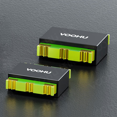
The three products below represent a no-light option, a 1×4 light-pipe option, and a 2×6 outer-dual-light option. Select according to port density and the intended front-panel indication. A product model identifies a particular configuration; the drawing, PCB hole pattern, connector arrangement, and assembled sample still need to remain consistent through design release.
| Application and Indication Need | VOOHU Product | Configuration and Selection Note |
|---|---|---|
| Single-port SFP28 with a separate panel indicator, or no port indicator required | WHSFP30211W031 | Cage; SFP28; 25G; Press-Fit; 1×1; no light pipe; ventilation openings; 30U" nickel plating. A straightforward option when indication is handled elsewhere on the panel. |
| 1×4 SFP+ ports that need PCB status LEDs routed to the front panel | WH81-114-Y0006-1 | Cage; SFP+; 10G; Press-Fit; 1×4; light pipes included; ventilation openings. Suitable for four ports in one row when LED positions, light-pipe exits, and panel apertures are matched as one assembly. |
| 2×6 high-density SFP28 ports using an outer dual-light indication scheme | WHSFP32326F002 | Cage+Connector; SFP28; 25G; Press-Fit; 2×6; outer dual-light configuration; ventilation openings; connector gold plating 30U" and nickel plating 50U". Intended for dense front panels whose indicator mapping is defined around the outer light positions. |
5. Validate the Indicators, Panel, and Module Access on the Same Sample
After assembly, activate Link or Activity on one port at a time and verify that every front-panel indicator maps to the correct port. Then illuminate adjacent ports together and inspect light leakage, brightness consistency, and whether upper/lower or left/right ports can be distinguished. This catches mapping errors before panel tooling and volume assembly.
Insert the intended optical modules during the same review. Confirm that the light pipes and panel do not interfere with the module latch, pull tab, or thermal hardware. For multi-port cages, inspect the full row from the front and recheck that each light-pipe output remains centered in its aperture after pressing or soldering. If the unit uses multiple colors or blink rates, test those patterns under the actual operating definitions.
VOOHU supplies SFP, SFP+, SFP28, and higher-density pluggable I/O connector options with multiple port counts, light-guide patterns, mounting methods, and thermal structures. Once the port layout and indication scheme are defined, the PCB and panel drawings can be matched to a suitable product to reduce mechanical rework and keep port status clear in use.
6. Frequently Asked Questions
Q1: How do I choose an SFP cage light pipe, and when is a no-light cage better?
Use a cage with light pipes when the panel needs direct port indication and the PCB provides LEDs at the matching locations. Use a no-light cage when the unit has separate indicators, a display, or a centralized status area. The port count, LED positions, and panel apertures must agree with the selected cage.
Q2: Why does one SFP light pipe make an adjacent port glow?
Common causes include an offset LED, insufficient optical separation, a light-pipe input that collects light from two LEDs, or a reflective inner panel surface. Activate one port at a time and mask neighboring channels to locate the leak before changing the LED position, barrier, or drive level.
Q3: Can SFP cages with the same port count be interchanged?
Port count alone is not enough. The SFP family, target data rate, cage or cage-plus-connector construction, mounting method, PCB hole pattern, light-guide configuration, thermal option, and panel dimensions all need to match.
Q4: Does a light pipe affect the SFP high-speed signal?
The light pipe does not carry the high-speed electrical signal. Incorrect assembly can, however, interfere mechanically with the cage, panel, thermal hardware, or module removal. Validate the optical guide together with the connector, PCB, panel, and cooling structure.