Common Mode vs Differential Mode Noise: How to Tell Them Apart and Which Filter Stops Each
Common Mode vs Differential Mode Noise: How to Tell Them Apart and Which Filter Stops Each
Differential mode noise travels the same way as the wanted signal or supply current: out on one conductor and back on the other. Common mode noise flows in the same direction on both conductors at once and returns through ground, the chassis or stray capacitance. Differential mode noise is filtered with X capacitors across the lines and differential mode inductors in series with them. Common mode noise is filtered with a common mode choke, which presents high impedance only to current flowing the same way on both lines, plus Y capacitors to ground on power inputs. To find out which one you have, measure the net current on the cable pair or separate the two modes on a LISN. VOOHU supplies signal-line and DC power-line common mode chokes with impedance stated at its test frequency, such as 1000 Ω typical at 100 MHz for the WHLC-2012A-102T0.
What is the difference between common mode noise and differential mode noise?
Any pair of conductors, such as a USB pair, a CAN bus or the two wires of a DC input, can carry current in two ways. A common-mode signal is the part that is identical on both conductors, measured against ground. A differential signal is the difference between the two.
- Differential mode currentflows out on one line and back on the other. The two currents are equal and opposite, so their magnetic fields largely cancel and the loop they enclose is small.
- Common mode currentflows the same way on both lines and has to find another way back, through the ground plane, the chassis, the earth wire or the stray capacitance between the circuit and its surroundings. The return path is long and loosely defined, so the loop is large.
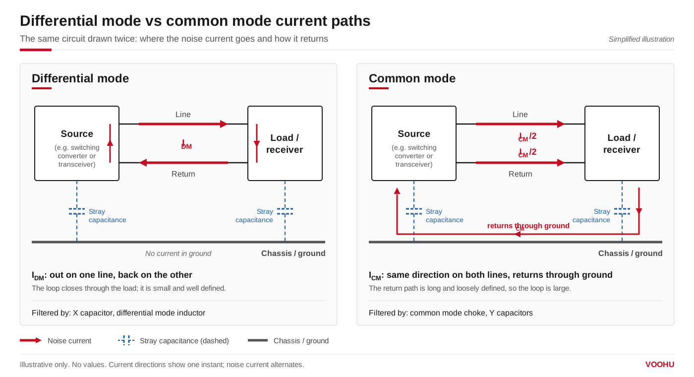
Differential mode current circulates between the two lines. Common mode current flows the same way on both lines and returns through ground or stray capacitance. Simplified illustration.
| Item | Differential mode noise | Common mode noise |
|---|---|---|
| Current path | Out on one line, back on the other | Same direction on both lines, back through ground or chassis |
| Typical sources | Pulsed input current of a switching converter, load current steps, signal harmonics | Fast voltage edges coupling through stray capacitance, ground potential differences, imbalance in a differential pair, external fields |
| Where it shows up in EMC tests | Mostly the lower part of the conducted emissions range | Higher conducted frequencies and most cable-related radiated emissions |
| Filter components | X capacitor across the lines, differential mode inductor in series | Common mode choke in the pair, Y capacitors to ground on power inputs |
| Effect of a common mode choke | Passes it, apart from a small effect of leakage inductance | Blocks it with the choke's common mode impedance |
What causes common mode noise?
Common mode noise is generated wherever a changing voltage or current can reach ground by a path other than the intended return:
- Switching edges and stray capacitance.In a switching power supply, the switch node swings by the full input voltage in nanoseconds. Its capacitance to the heatsink, the chassis or the transformer's other winding injects current pulses into ground, and they come back as common mode current on the input and output cables.
- Ground potential differences.When two boards or two units are grounded at different points, the voltage between those grounds drives current along the cable that connects them.
- Imbalance in a differential pair.If the two lines of a pair differ in length, loading or edge timing, part of the differential signal is converted into common mode.
- External fields.A field from a nearby source couples almost equally into both conductors of a cable, which is by definition a common mode signal.
What causes differential mode noise?
Differential mode noise comes from the circuit's own operating current. A switching converter draws its input current in pulses; the input capacitor cannot supply all of it, so part of the ripple flows back through the input wires as differential mode noise. Fast load steps on a supply rail and the harmonics of a digital signal travel the same way. Because the source is the wanted current path, differential mode noise grows with load current and is usually filtered close to where it is generated.
Why is common mode noise bad?
Because common mode current does not cancel. The equal and opposite currents of a differential signal produce fields that mostly cancel a short distance away; common mode current flows the same way on every conductor of the cable, so the cable behaves like an antenna. A common mode current far smaller than the signal current can therefore radiate more than the signal itself, which is why cable-related radiated emission failures are usually common mode problems. On a power line, common mode noise also leaks into the mains and into other equipment through the protective earth, and on a data line it shifts both inputs of the receiver together until it can corrupt data.
How do you measure common mode noise?
- Current probe around the pair.Clamp an RF current probe around both conductors of the cable together. The differential currents cancel inside the probe, so what you read is the common mode current. Clamp it around one conductor only and you read differential plus half of the common mode current.
- LISN and mode separation.In a conducted emissions setup, the LISN gives the noise voltage of each line to ground. Half their sum is the common mode component and half their difference is the differential mode component; a noise separator network between the LISN outputs and the receiver does this in hardware.
- Swap the filter.Add a common mode choke, or an X capacitor, and see which peaks move. A peak that drops with the choke is common mode; one that drops with the X capacitor is differential mode.
How to reduce common mode noise, and differential noise
Start at the source: slow down switching edges where the design allows, keep switch nodes small and away from the chassis, route differential pairs symmetrically and give every signal a short, continuous return path. Then filter what is left with the component that matches the mode:
| Noise and line | Common mode vs differential mode filter | What to check |
|---|---|---|
| Differential mode, DC or AC power input | X capacitor across the lines; differential mode inductor in series; enough bulk capacitance at the converter | The inductor carries the full load current, so its saturation current must cover the peak input current |
| Common mode, power input | Common mode choke in both lines, Y capacitors from each line to chassis or ground | Rated current and DC resistance of the choke; Y capacitor values are limited by the allowed leakage current |
| Common mode, high-speed data pair (USB and similar) | Signal-line common mode choke | Common mode impedance at the frequency of the emission; low differential loss at the data rate |
| Common mode, CAN, CAN FD, LVDS | Signal-line common mode choke in the bus pair | Common mode impedance and rated current; compare parts at the same test frequency |
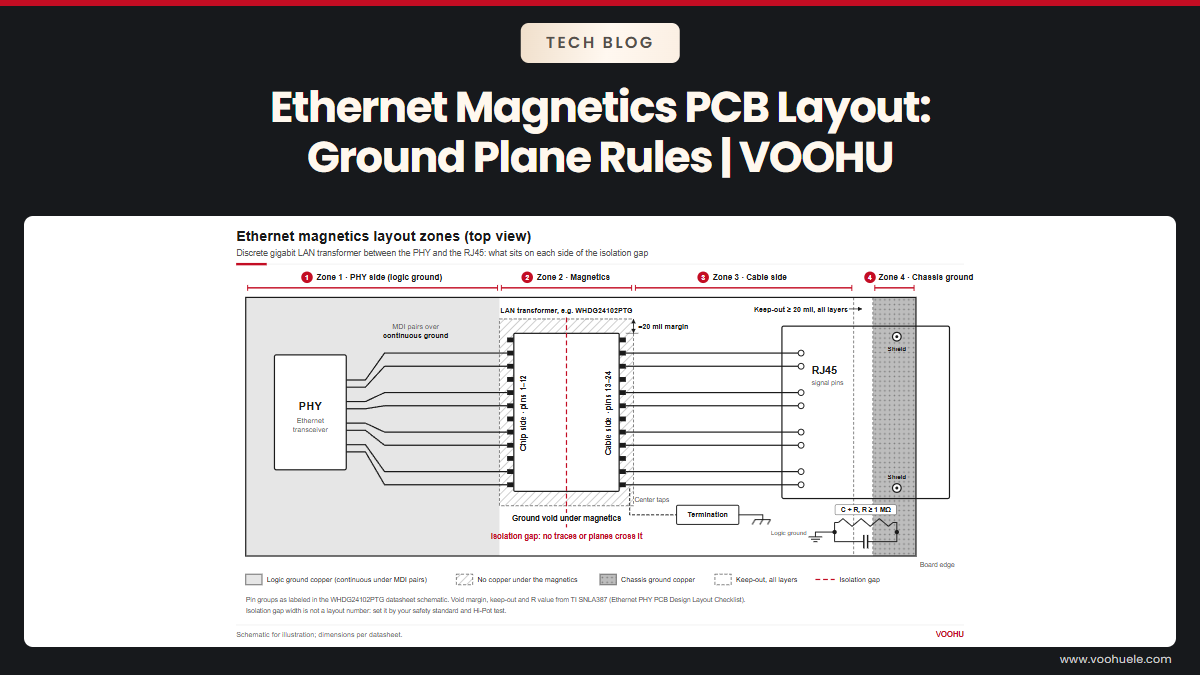
| Common mode, Ethernet | Common mode choke in the LAN transformer channel | Seewhere the common mode choke sits in a LAN transformer |
When to use a common mode choke?
Use a common mode choke when the measurement points to common mode, when a cable leaves the enclosure and radiated emissions are the concern, or when a power input fails the upper part of the conducted range. Because the wanted current passes through it with its fields cancelling, a common mode choke filters noise on a signal or supply pair without loading the signal much or saturating on the DC current. For how the windings and core achieve this, seewhat is a common mode choke.
Which VOOHU common mode choke fits which line?
The table lists four VOOHU common mode chokes by line type, with the common mode impedance at the test frequency stated on each datasheet. Compare impedance between parts only at the same test frequency.
| Line | Part | Common mode impedance | Rated current | Rated voltage | DC resistance | Size (mm) |
|---|---|---|---|---|---|---|
| High-speed differential signal pair | WHLC-2012A-102T0 | 1000 Ω typ at 100 MHz | 300 mA max | 50 Vdc | 1.3 Ω max | 2.00 × 1.20 × 1.20 (0805) |
| CAN, CAN FD, LVDS differential lines (listed on the datasheet) | WHAC-3225B-110U0 | 550 Ω typ, 300 Ω min, at 10 MHz | 300 mA max | 80 V max | 0.8 Ω max | 3.25 × 2.50 × 2.30 |
| DC power line, compact | WHAL-4520A-302T0 | 3000 Ω typ, 2500 Ω min, at 100 MHz | 1.0 A | 50 V max | 80 mΩ max | 4.7 × 4.5 × 2.5 max |
| DC power line | WHACM07A40R302 | 3000 Ω ref, 2500 Ω min, at 100 MHz, 0.1 V | 0.9 A max DC | 125 V max | 75 mΩ max | 7.0 × 6.0 × 4 max |
The WHLC-2012A series covers 90 Ω to 1200 Ω typical at 100 MHz in the 0805 size, so you can step the impedance up or down to match the emission you need to remove; compare them in thesignal-line common mode choke selector. For DC inputs, filter thepower-line common mode chokesby size and check the rated current against your input current. For a full walk-through of a DC input filter, seepower line common mode chokes for DC conducted emissions; for USB, seehow to choose a USB 2.0 common mode choke.
产品WHAC-3225B-110U0
产品WHAL-4520A-302T0
FAQ
Q1: What is common mode noise rejection?
It is the ability of a differential receiver or amplifier to ignore a voltage that appears equally on both of its inputs, usually given as the common mode rejection ratio (CMRR). It is why differential signaling tolerates noise, but it only works while the common mode voltage stays inside the receiver's input range and while the pair stays balanced. A common mode choke adds rejection before the receiver and also reduces what the cable radiates, which the receiver's CMRR cannot do.
Q2: Common mode vs differential mode choke: what is the difference?
A common mode choke has two windings on one core, connected so that the wanted current cancels in the core; it only presents high impedance to common mode current and does not saturate on the load current. A differential mode choke is a single inductor in series with a line; the full load current magnetizes its core, so it must be sized for that current. A common mode choke's leakage inductance gives some differential attenuation, but it is not a substitute for a differential mode inductor when differential noise is the problem.
Q3: Does a common mode choke have polarity?
Yes, in the sense of winding direction. The two windings must be connected so that the wanted current flows in one and returns through the other in the opposite sense, which is shown by the dots or the pin numbering on the datasheet drawing. If one winding is reversed, the wanted current no longer cancels in the core, so the choke acts as a series inductor for the signal or supply and can saturate. Swapping the whole part end for end, input for output, does not matter. For how the windings cancel, seewhat is a common mode choke.
Get samples of the right common mode choke
Tell us the line you need to filter, signal pair or DC input, its operating current and the frequency range where your emissions fail in thesample and support request form. Our FAE team can suggest common mode chokes with the impedance and rated current that fit your line, and check the footprint and winding orientation in your layout. Samples are available for evaluation, and selected parts are free of charge. Our FAE team will be glad to confirm the options for your project.
VOOHU supplies RJ45 and SFP connectors, LAN and PoE transformers and common mode chokes from Suzhou, China, to more than 1,500 customers.
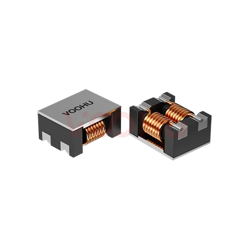 WHACM07A40R302 Dimensions7.0±0.5*6.0±0.5*4 DC Resistance 75mΩ Rated DC Current 0.9A Common Mode Chokes
> View Details
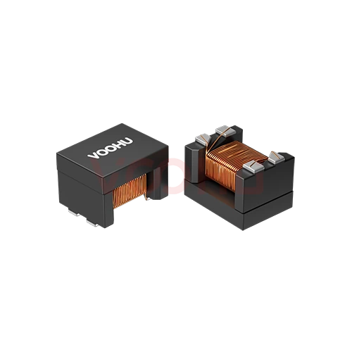 WHAC-3225B-110U0 Inductance11uH RDC0.8Ω Leakage Inductance50nH Common Mode Chokes
> View Details
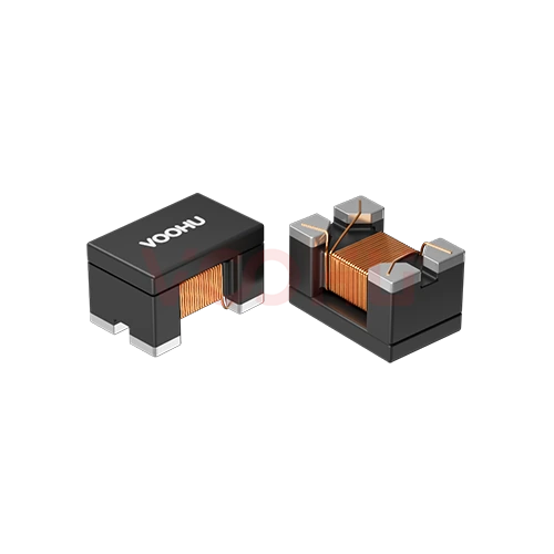 WHLC-2012A-102T0 100/1000BASE-T Cap+CMC Size2012(0805) Impedance(Ω)1000 non-PoE
> View Details
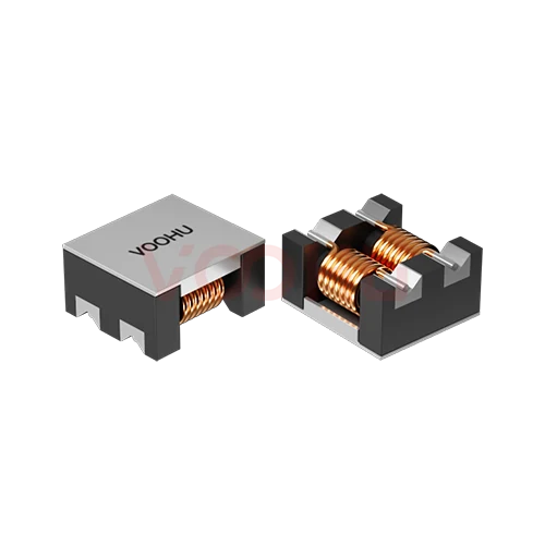 WHAL-4520A-302T0 Dimensions4.7±0.5*4.5±0.5*2.5 DC Resistance 80mΩ Rated DC Current 1.0A
> View Details