
What Is a Common Mode Choke and How Does It Work?
A common mode choke (CMC) is an inductor with two windings on one shared magnetic core, connected in series with a pair of conductors such as a differential data pair or the two lines of a power input. The wanted current flows out on one conductor and back on the other, so its magnetic fluxes cancel in the core and the choke adds very little impedance. Noise that flows in the same direction on both conductors, called common mode noise, produces fluxes that add, so the choke presents a high impedance and blocks it. That is why a CMC can suppress EMI on a cable or supply line without dropping the signal or the supply. Common mode chokes fall into two groups: signal line chokes for data interfaces such as USB, CAN, Ethernet and HDMI, and power line chokes for AC or DC supply inputs.
How does a common mode choke work?
Every pair of conductors can carry two kinds of current at once.
- Differential mode currentis the current you want: the signal or the supply current, traveling out on one conductor and returning on the other.
- Common mode currenttravels in the same direction on both conductors and returns through another path, usually ground, chassis or the parasitic capacitance between the circuit and its surroundings.
In a common mode choke both conductors are wound on the same core with the same number of turns and the same winding sense. For differential current, the two windings carry equal and opposite currents, so their magnetic fluxes cancel and the core sees almost no net magnetization. For common mode current, the two currents point the same way, the fluxes add, and the winding behaves like a large inductor.
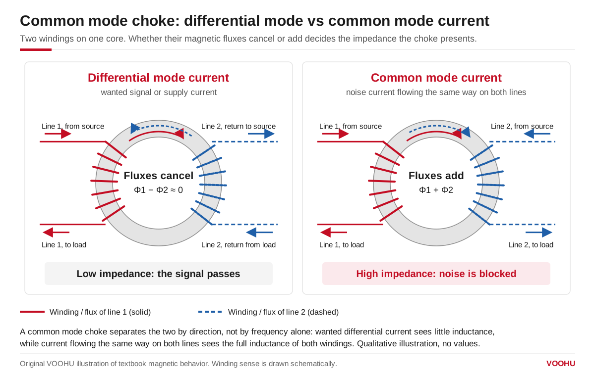
A common mode choke passes differential current because the fluxes of its two windings cancel, and blocks common mode noise because they add.
At higher frequencies the impedance of a ferrite-core CMC is not purely inductive. Core losses add a resistive part, and in the band where that resistance dominates the choke absorbs noise energy and turns it into heat rather than reflecting it back into the circuit. This is one reason datasheets show impedance as a curve over frequency instead of a single inductance value.
The cancellation is never perfect. Leakage inductance, the part of each winding that does not couple to the other, sits in series with the differential path: it adds a little differential filtering, but on a fast data line it must stay low enough not to distort the signal.
What is the common mode choke symbol?
The usual schematic symbol is two inductor coils drawn side by side, with one or two straight lines between or beside them to show a shared magnetic core. Dots mark the start of each winding, and both dots sit on the same end. Common mode current enters both dotted ends together, so its fluxes add; differential current enters one dotted end and leaves by the other, so its fluxes cancel.
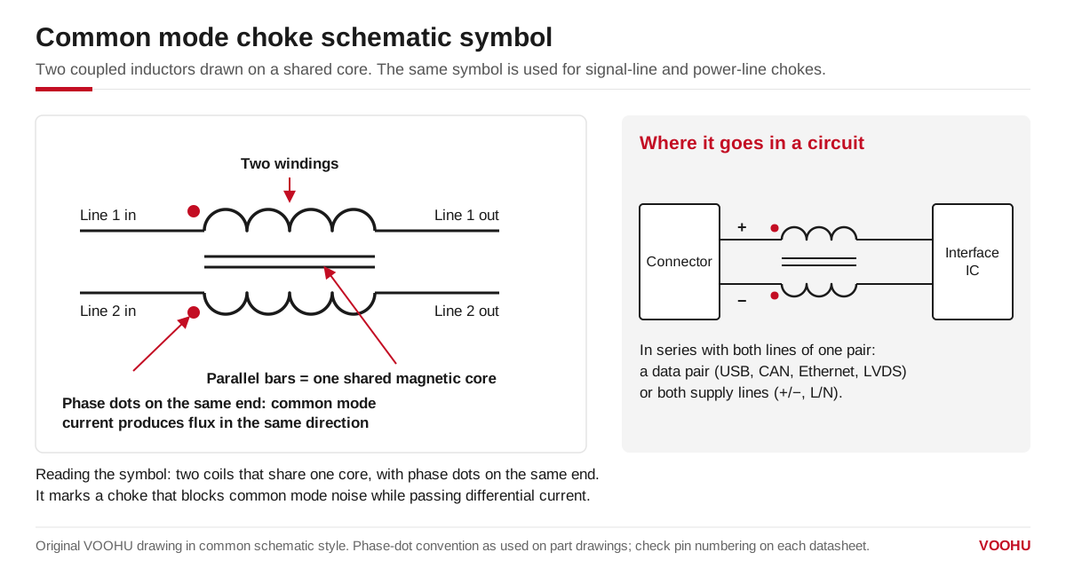
Two coils on one core with phase dots on the same end mark a common mode choke, placed in series with both lines of a pair.
Reference designators are usually L, and some schematics use FL for filter parts. Pin numbering is not standardized across packages: on one 4-pin part the windings may run 1–2 and 3–4, on another 1–4 and 2–3. Check the pin assignment in the datasheet before drawing the footprint.
Where does common mode noise come from?
It usually comes from one of three mechanisms:
- Switching edges coupling to ground.A fast-switching node in a power converter drives current through parasitic capacitance to the heat sink, chassis or earth, and that current returns through both supply lines together.
- Imbalance in a differential pair.Unequal capacitance or trace length on the two lines converts part of the differential signal into common mode.
- Ground potential differences.Two units joined by a cable rarely sit at the same ground potential, and the difference drives current along the whole cable.
Once common mode current reaches a cable, the cable acts as an antenna, which is why emission scans can fail even when the differential signal is clean.
Signal line vs power line common mode chokes
The physics is the same in both groups; what differs is what the choke must pass.
| Aspect | Signal line common mode choke | Power line common mode choke |
|---|---|---|
| Typical lines | Differential data pairs: USB, CAN, Ethernet, HDMI, LVDS | AC mains input, DC supply rails, motor drive and inverter inputs |
| What must pass cleanly | A data signal, with low differential loss and low mode conversion | DC or line-frequency current at full load |
| Ratings to check first | Common mode impedance vs frequency, differential insertion loss, mode conversion, DC resistance | Common mode impedance vs frequency, rated current, DC resistance, withstand voltage |
| Typical construction | Small SMD parts | SMD and toroidal parts; larger cores for higher current |
| Main risk if mis-selected | Signal distortion, reduced eye opening, failed compliance at the data rate | Core saturation and overheating, impedance collapse under load |
| VOOHU category | signal line common mode chokes, grouped by interface (USB, CAN, Ethernet, HDMI) | power line common mode chokes, families in size bands from 1211 to 9070 |
On Ethernet ports the choke is often built into the LAN transformer or the MagJack (integrated magnetics RJ45). For interface-level selection on USB, seechoosing a common mode choke for USB 2.0.
How do you read a common mode choke datasheet?
Four ratings decide most selections.
- Common mode impedance and its test frequency.Impedance is a curve, and the headline value is measured at one stated frequency and signal level. The VOOHU WHACM07A40R302 power line common mode choke, for example, lists impedance at 100 MHz and 0.1 V, with both a minimum and a reference value. For signal line parts, see the datasheet for the test frequency. Only compare two parts at the same frequency; a figure at 10 MHz and a figure at 100 MHz describe different points on different curves.
- Rated current.The continuous current the winding carries under stated temperature-rise conditions. On power lines this is usually the limiting rating.
- DC resistance (DCR).Usually a maximum value. It sets the voltage drop and the conduction loss at full load.
- Withstand voltage or insulation resistance.On mains-connected power line chokes this rating has to meet the safety requirement of the equipment.
For signal line chokes, also look for differential insertion loss and, on fast interfaces, mode conversion data.
Common mode choke vs ferrite bead
A ferrite bead is a single conductor through a ferrite core. It has no second winding to cancel against, so it adds impedance to whatever current flows through it, wanted or not.
| Question | Common mode choke | Ferrite bead |
|---|---|---|
| Number of conductors | Two (or more) on one core | One |
| Effect on differential signal | Low, because fluxes cancel | Adds impedance to the signal itself |
| Effect on common mode noise | High impedance | High impedance, but only on the line it sits on |
| Saturation by DC load | Load current largely cancels in the core | Full DC current biases the core, lowering impedance |
A bead on each line of a differential pair attenuates the signal along with the noise, so data pairs normally use a common mode choke. On a single power rail that needs high-frequency decoupling, a bead is often the simpler choice.
FAQ
Q1: Is a common mode choke the same as a common mode inductor?
Yes. "Common mode choke," "common mode inductor" and "CMC" describe the same component. "Common mode filter" has two uses: many manufacturers use it as another name for the choke itself, especially for small signal line parts, while others mean a complete filter network that adds Y capacitors around the choke.
Q2: Does a common mode choke filter differential noise?
Only slightly. Its leakage inductance adds a small series inductance to the differential path, which gives some attenuation at high frequencies, but the choke is not designed for that job. Differential noise on a power input is normally handled with X capacitors and, if needed, a separate differential mode inductor.
Q3: What happens if a common mode choke is connected the wrong way around?
If one winding is reversed, differential current no longer cancels in the core. The choke then acts as a large inductor in the signal or supply path: on a data line it distorts the signal, and on a power line the load current can saturate the core so the filtering collapses and the part heats up. Follow the polarity dots and the pin assignment in the datasheet.