




Common mode impedance
The resistance the choke presents to common mode noise, quoted at a stated frequency. Compare candidates at the same frequency or the values do not correspond.
Induktivitätsprodukte
A common mode choke blocks noise that travels the same direction on both conductors while letting the supply current pass. Start from the frequency band your measurement actually fails, pick the impedance that covers it, then check rated current and DC resistance against the load the line has to carry.
Artikelsuche und Produktauswahl
Die Tabelle verwendet die aktuellen Produktdatensätze der englischsprachigen Website, veröffentlichte Auswahlfelder und artikelspezifische Links zu technischen Dateien.
* Spalten „Bild“ und „Artikelnummer“ fixiert · horizontal ziehen, um alle Spezifikationen anzuzeigen
| Bild | Datenblatt | Vergleichen | Downloads |
Abmessungen (L×B×H, max.)
|
Z (Ω) bei 100 MHz/0,1 V, min.
|
Z (Ω) bei 100 MHz/0,1 V, Referenzwert
|
Gleichstromwiderstand (mΩ), max.
|
DC-Nennstrom (A), max.
|
Isolationswiderstand (MΩ), min.
|
Nennspannung (V), max.
|
Muster |
|---|
| Bild | Artikelnummer | Datenblatt | Vergleichen | Downloads | Abmessungen (L×B×H, max.) | Z (Ω) bei 100 MHz/0,1 V, min. | Z (Ω) bei 100 MHz/0,1 V, Referenzwert | Gleichstromwiderstand (mΩ), max. | DC-Nennstrom (A), max. | Isolationswiderstand (MΩ), min. | Nennspannung (V), max. | Muster |
|---|---|---|---|---|---|---|---|---|---|---|---|---|
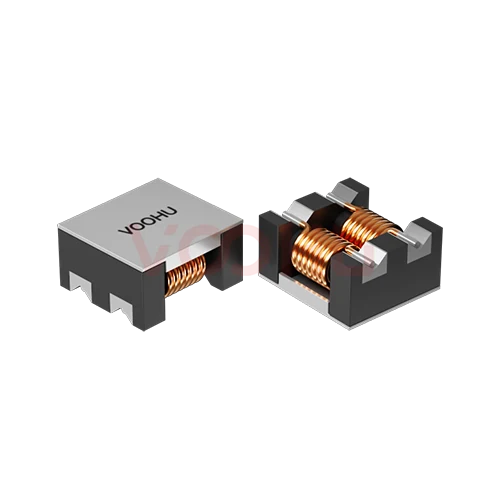 |
WHACM15A60R152 | SPEC | 1513 | 1200 | 1500 | 23 | 5 | 10 | 80 |
|
||
|
|
WHACM15A60R102 | SPEC | 1513 | 800 | 1000 | 10 | 9 | 10 | 80 |
|
||
|
|
WHACM15A60R701 | SPEC | 1513 | 500 | 700 | 7 | 10 | 10 | 80 |
|
||
|
|
WHACM15A60R501 | SPEC | 1513 | 400 | 500 | 6 | 10 | 10 | 80 |
|
||
|
|
WHACM15A60R301 | SPEC | 1513 | 225 | 300 | 5 | 13 | 10 | 80 |
|
Erweitern Sie die ausgewählten Filter oder löschen Sie die aktuelle Suche.
By series
Families differ in construction and size band, which sets impedance and current together.
So wählen Sie aus
Work from the failing frequency band outward to current, losses and board space.
Read the frequency range where your conducted emission scan exceeds the limit. That band, not a general noise complaint, decides which impedance curve you need.
Pick a part whose common mode impedance peaks across the failing band. Read the impedance at that frequency, not the headline figure at the family's peak.
The rated current must cover the worst-case load with margin. DC resistance sets the voltage drop and the heat the winding has to shed.
Check size, land pattern and clearance to neighbouring parts, then re-scan on your own board because layout changes the result.
Parameters
Impedance is a curve, not a single number, so read the test frequency with the value.
The resistance the choke presents to common mode noise, quoted at a stated frequency. Compare candidates at the same frequency or the values do not correspond.
The continuous current the winding carries under stated temperature-rise conditions. Derate for ambient temperature and restricted airflow inside the enclosure.
Winding resistance, usually a maximum figure. It sets the conduction loss and the voltage drop the supply has to tolerate at full load.
Measured with both windings in the common mode configuration. Higher inductance generally moves the impedance peak toward lower frequencies.
The part of the winding that does not couple. It acts on differential signals and can be useful, but it also limits how high a current the part handles.
Isolation between the two windings under a stated test. Select against the safety requirement that applies to the equipment, not the working voltage.
Vergleichen
Size band drives impedance and current capability more than family naming does.
Zur Produktauswahl zurückkehren ↑| Abmessungen (L×B×H, max.) | Artikelnummern | Z (Ω) bei 100 MHz/0,1 V, min. | Z (Ω) bei 100 MHz/0,1 V, Referenzwert | Gleichstromwiderstand (mΩ), max. | DC-Nennstrom (A), max. | Isolationswiderstand (MΩ), min. | Nennspannung (V), max. | Aktion |
|---|---|---|---|---|---|---|---|---|
| 1211 | 7 | 80, 500, 600, 750, 2200, 2300 | 230, 700, 800, 1000, 2500, 2700 | 2, 4, 6, 8, 14, 35, 50 | 1.5, 1.8, 6, 8, 10 | 10 | 125 | Filtern → |
| 1513 | 5 | 225, 400, 500, 800, 1200 | 300, 500, 700, 1000, 1500 | 5, 6, 7, 10, 23 | 5, 9, 10, 13 | 10 | 80 | Filtern → |
| 4520 | 14 | 60, 90, 180, 200, 250, 300, 350, 500, 650, 800, 1000, 1200, 1800, 2500 | 90, 150, 230, 300, 380, 420, 500, 700, 900, 1000, 1200, 1400, 2000, 3000 | 35, 40, 45, 50, 55, 58, 60, 70, 80 | 1, 1.5, 1.9, 2.0, 2.1, 2.2, 2.4, 2.5, 3, 3.2 | 10 | 50 | Filtern → |
| 7060 | 9 | 40, 100, 225, 275, 500, 800, 910, 2000, 2500 | 70, 140, 300, 450, 700, 1020, 1300, 2700, 3000 | 5, 10, 15, 17, 21, 63, 75 | 0.9, 1, 2.5, 3, 4, 5, 9, 15 | 10 | 125 | Filtern → |
| 9070 | 6 | 225, 450, 500, 750, 1700, 2500 | 300, 600, 700, 1000, 2200, 3000 | 6, 8, 10, 13, 60, 75 | 2.5, 3, 4, 5, 5.5, 6 | 10 | 50 | Filtern → |
Anwendungsprüfung
Confirm the line current, the failing band and how much board space the filter can take.
Documents
Datasheets carry the impedance curve, current rating and recommended land pattern.
Es werden repräsentative verfügbare Dateisätze angezeigt. Suchen Sie nach einer bestimmten Artikelnummer.
Die veröffentlichten Produktinhalte von VOOHU werden vom technischen Team geprüft. Spezifikationen, Downloads und Informationen zum technischen Support sind bestimmten Artikelnummern zugeordnet, sodass Sie sie vor einer Muster- oder Angebotsanfrage prüfen können.
Kategorieübersicht
Most selection mistakes here come from treating impedance as a single number, or from confusing common mode with differential mode noise.
Neues Design besprechen
FAE für eine Ersatztypenprüfung kontaktieren.
Sie haben bereits eine Artikelnummer? Muster oder Angebot anfragen.
Differential noise travels out on one conductor and back on the other. Common mode noise travels the same direction on both and returns through ground. A choke winds both conductors on one core so their supply currents cancel, while common mode current sees a high impedance. That is why it filters one and passes the other.
The headline impedance figure is measured at one frequency. What matters is whether the curve is high across the band where your conducted emission scan actually fails. A part with a higher peak in the wrong place will not help. Read the curve from the datasheet, identify your failing band first, and match the two.
Rated current and DC resistance set the ceiling. A choke with excellent impedance is useless if the winding cannot carry the load current, or if its resistance drops the rail below tolerance. Check those against worst case, then confirm on your own board, because layout and the rest of the filter change the measured result.
FAQ
Answers cover how the choke works, how to read impedance and where it belongs.
It winds both conductors of a line on one shared core. Supply current flows out on one and back on the other, so the two magnetic fields cancel and the choke is almost invisible to it. Common mode noise flows the same direction on both conductors, its fields add, and the choke presents a high impedance that blocks it.
Differential noise travels out on one conductor and back on the other, between the two lines. Common mode noise travels the same direction on both and returns through ground or chassis. A common mode choke is built to block the second kind while passing the first, which is why it filters supply lines without dropping the supply.
Impedance is a curve across frequency, and the headline number is measured at one stated point. Start from the frequency band where your conducted emission scan fails, then read each candidate's impedance at that frequency. A part with a higher peak somewhere else will not fix your specific failure.
In everyday use the terms overlap, but a filter usually means the whole network, including Y capacitors and sometimes a differential inductor, while the choke is one component in it. When you specify a part, specify the choke. When you design the stage, think about the whole filter and how its parts interact.
The winding has to carry the full supply current continuously. Exceeding the rated current drives temperature rise beyond what the part was qualified for, and in ferrite parts it can push the core toward saturation, at which point the impedance collapses and the filtering stops working. Derate for the real ambient temperature.
Toroidal parts generally offer higher impedance and current capability for a given cost, at the price of board area and height. SMD parts suit automated assembly and tighter boards. Start from the impedance and current you need, then let the mechanical constraints decide which construction fits.
Because the measured result depends on the whole loop, not just the component. Layout, the position of the filter relative to the noise source, the ground return path and the rest of the filter network all change what the scan sees. Always confirm on the real board in the real enclosure.
With a complete part number, send the part number, quantity, delivery region and the date you need it. If you are still selecting, send the line voltage and current, the frequency band where your scan fails and the space available on the board, and a sales engineer will shortlist candidates.
Technischer Support
Senden Sie die Artikelnummer des Kandidaten und die zu prüfende Bedingung. Muster können nach Abschluss der Auswahl angefragt werden; kaufmännische Fragen lassen sich im selben technischen Austausch klären.
Dokumentrevision angeben
Temperatur, Isolationsspannung und Bezugsgrundlage für den PoE-Strom
Pinzahl, Rastermaß und Abstand zwischen den Pinreihen
Zur Priorisierung von Mustern und Evaluierung
Zeitpunkt, zu dem Sie Kandidaten und einen Vergleich der Unterschiede benötigen
Die technische Prüfung ermittelt geeignete Kandidaten und erläutert die Unterschiede.
Aus der Produktauswahl oder technischen Prüfung
Prototyp / Pilotserie / Serienfertigung
Zeitplan für Muster und Serie getrennt angeben
Konformitätsnachweise, Materialdeklarationen oder Berichte Dritter
Mustermenge, Lieferzeit und Kosten hängen von der Projektphase und der Artikelnummer ab. Der Vertrieb antwortet an Werktagen.




