PoE Ethernet Port Design: Six Questions Engineers Ask Most
Surveillance cameras are adding pan-and-tilt heaters, wireless access points are moving to Wi-Fi 7, and EV charging stations and building controllers are carrying power and data over the same Ethernet cable.Power over Ethernet (PoE)is no longer just about whether power can be delivered. It is about getting the power budget right.
The following six questions cover the issues hardware engineers encounter most often in PoE Ethernet port design, from the underlying principles to practical component selection.
Q1. How does a PoE LAN Transformer differ from a standard LAN Transformer? Are they interchangeable?
They should not be treated as interchangeable.The package and pin arrangement may look identical, but the important difference is inside the magnetic core.
A standard, non-PoE LAN Transformer carries differential data signals; its windings do not have to carry the PoE supply current. In a PoE link, DC power is fed through the center taps into the windings. DC bias shifts the core's operating point along its hysteresis loop. As that operating point approaches saturation, the effective permeability seen by the AC signal falls, reducing the magnetizing inductance, specified as open-circuit inductance (OCL).
This inductance is important to low-frequency performance. As it falls, insertion loss and return loss around 1 MHz are among the first parameters to deteriorate; common-mode rejection may also worsen. Using a non-PoE transformer in a PoE port is therefore not simply a question of whether the equipment powers up. The question is whether the link remains stable at full power load.
In the other direction, a PoE-rated LAN Transformer will generally work electrically in a non-PoE port. However, the extra core and winding cost required for DC-bias capability may be unnecessary, and its inductance specification may not be the best fit for the non-PoE design.
The first selection check should therefore be the specified DC-bias capability, not just the package.
Q2. Which PoE standards do 350 mA, 720 mA and 1200 mA ratings correspond to?
First, establish exactly what the stated current represents.
For example, the PoE current parameter for VOOHULAN Transformersis the total DC-bias current for the whole port, not the current per twisted pair or per pairset.
Manufacturers do not always use the same convention. A 600 mA rating expressed per pair represents 2.4 A across four pairs, whereas a 600 mA whole-port rating does not reach the Type 3 level. That is a fourfold difference. Always confirm the rating basis before comparing products from different manufacturers.
Once the ratings have been expressed on a whole-port basis, approximate current thresholds can be calculated. For the estimates below, use a nominal PSE output of 52 V and a worst-case PD input of 42.5 V, or 44 V for Type 1. Calculate current at both ends and use the larger result.
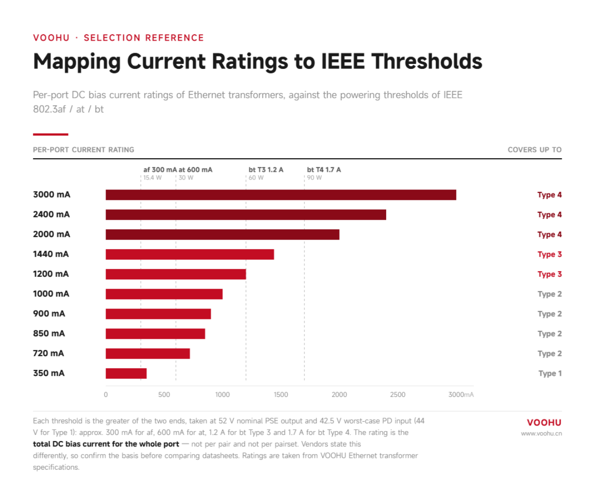
Whole-port current ratings and the PoE levels they cover
Reference thresholds used here: 802.3af, approximately 300 mA at 15.4 W; 802.3at, approximately 600 mA at 30 W; 802.3bt Type 3, approximately 1.2 A at 60 W; and Type 4, approximately 1.7 A at 90 W.
| Standard | Type | Powered pairs | PSE output | Power available at PD | Approx. whole-port current threshold |
|---|---|---|---|---|---|
| 802.3af | Type 1 | 2 pairs | 15.4 W | 12.95 W | 300 mA |
| 802.3at | Type 2 | 2 pairs | 30 W | 25.5 W | 600 mA |
| 802.3bt | Type 3 (Class 5–6) | 4 pairs | 60 W | 51 W | 1.2 A |
| 802.3bt | Type 4 (Class 7–8) | 4 pairs | 90 W | 71.3 W | 1.7 A |
These figures explain the common rating steps. A 350 mA rating provides roughly 17% margin over the af threshold, and 720 mA provides 20% over the at threshold. A 1200 mA rating, however, sits exactly on the Type 3 threshold, with no margin. Passing a steady-state test at room temperature may not be enough at full load and high temperature, because the core's saturation flux density falls as temperature rises. Where the data rate and package allow, consider 1440 mA or higher for Type 3 applications.
Q3. When upgrading to 802.3bt at 90 W, which components need to be reviewed?
Start by tracing the current path. The data and power paths meet at the LAN Transformer's center taps, where power carried by the four twisted pairs enters the PD-side supply path.
Five parts of this path need to be checked.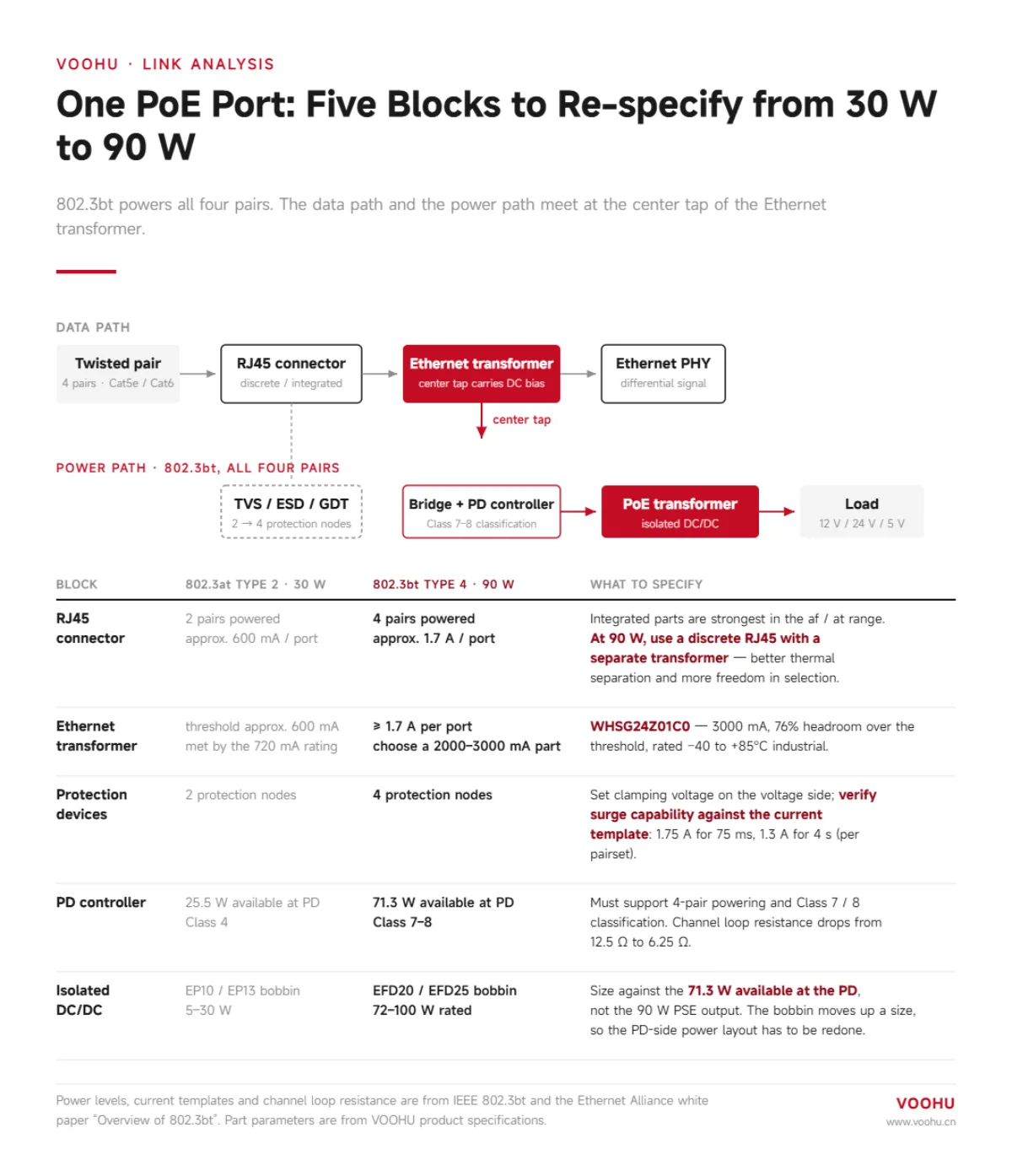
LAN Transformer.The whole-port current rating needs to reach at least the approximately 1.7 A level. For Type 4 applications, VOOHU recommendsWHSG24Z01C0: 100/1000 BASE-T, single port, 24 pins, 4PPoE up to 3000 mA, and −40°C to +85°C operation. Its current rating provides approximately 76% margin over the threshold, while the industrial temperature range suits outdoor pole-mounted equipment and hot locations inside enclosures.
RJ45 Connector.A discrete connector is recommended for 90 W designs.
PD controller.It must support four-pair power and Class 7/8 negotiation. In four-pair operation, the channel loop resistance falls from 12.5 Ω to 6.25 Ω.
Isolated DC/DC.Select it according to the power available at the PD, as discussed in Q6.
Protection devices.Four-pair power increases the protection nodes from two groups to four, leaving a tighter parasitic-capacitance budget for each device.
Evaluate protection in two dimensions. On the voltage side, set the clamping requirement using the upper limit of the PSE output voltage, including overshoot caused by cable inductance. On the current side, check capability against the 802.3bt transient profile: Type 3 has a continuous current limit of 0.85 A per pairset, while Type 4 permits 1.75 A for up to 75 ms and 1.3 A for up to 4 seconds. The TVS peak pulse-current capability and GDT current-handling capability must accommodate these windows.
Selecting protection solely by steady-state operating voltage can leave the design vulnerable at the moment of hot-plugging.
Q4. Why does the Ethernet link drop only at full power load, yet pass testing with no load?
This is a typical field symptom of the mechanism described in Q1: insufficient DC-bias margin.
At full power load, bias pushes the core toward saturation, OCL falls, and low-frequency insertion loss and return loss deteriorate. The link may negotiate a lower speed or experience a higher bit-error rate. Remove power for a retest, and the bias disappears, allowing the parameters to pass again. Because the fault occurs only under the combined condition of full data traffic and full power load, it can be difficult to isolate.
To reproduce the problem, apply the actual whole-port current required by the target PoE Type through the center taps. Under that bias condition, remeasure insertion loss and return loss from 1 MHz to 100 MHz. Overlay the results with the no-load curves and examine the deterioration at the low-frequency end.
Q5. Does “ALL” in the PoE field of VOOHU's RJ45 selection table mean the connector supports PoE?
No.In this selection field, “ALL” means that the connector itself does not impose a PoE current category.
A discrete RJ45 Connector contains no transformer, so transformer DC-bias capability does not apply to the connector itself. The PoE limit of this link is primarily determined by the LAN Transformer used with it. A stated PoE current becomes a selection parameter of the connector assembly itself when the RJ45 integrates the magnetics, as in a MagJack.
Which approach should you choose? An integrated RJ45 has its clearest advantages in the af/at range: it saves PCB area, eliminates one set of differential traces requiring length matching and impedance control, and reduces the component count by one. At 90 W, a discrete approach is recommended for practical thermal reasons: heating in the connector contacts and transformer windings no longer accumulates inside the same package.
Within VOOHU's selection range, separate LAN Transformers are available with ratings up to 3000 mA, while integrated RJ45 products are listed up to 1.5 A. The operating temperature ranges of the separate connector and transformer can also be matched independently.
A four-step selection sequence
- Set the PoE Type.Calculate the PSE-side and PD-side currents and use the larger value: 30 W → approximately 600 mA; 60 W → approximately 1.2 A; 90 W → approximately 1.7 A.
- Set the data rate.100/1000 Mb/s, 2.5G/5G and 10G designs have different pin-count and inductance requirements.
- Confirm the package and port configuration.Single or dual ports, SMD or DIP mounting, and pin pitch are constrained by the PCB layout; a larger device may not fit.
- Confirm the operating temperature.Complete the industrial-temperature check, including the −40°C lower limit where required, so the selected electrical and mechanical configuration also fits the environment.
| Typical application | Power requirement | Data rate / temperature | Ethernet interface approach | Isolated DC/DC |
|---|---|---|---|---|
| Indoor access points and IP phones Ceiling-mounted; temperature-controlled environment |
802.3at · 30 W | 100/1000 Mb/s Commercial: 0°C to +70°C |
An integrated MagJack is sufficient. A 720 mA rating saves PCB area and routing. | EP13 bobbin, 30 W class. Select using the 25.5 W available at the PD. |
| HD PTZ cameras and pan-and-tilt heaters Outdoor pole mounting; large day/night temperature swings |
802.3bt Type 3 · 60 W | 2.5G / 5G Industrial: −40°C to +85°C |
Discrete RJ45 + WHSQ48802C1 Dual ports, 48 pins, 4PPoE 1200 mA, −40°C to +85°C. This is VOOHU's highest rating at this data rate; evaluate derating at full load and high temperature. |
EFD20 / EFD25, 60 W WHTSE030, WHEFD25020 |
| High-power access points and EV charging stations Continuous full-load power; outdoor use |
802.3bt Type 4 · 90 W | 100/1000 Mb/s Industrial: −40°C to +85°C |
Discrete RJ45 + WHSG24Z01C0 Single port, 24 pins, 4PPoE 3000 mA, −40°C to +85°C. |
WHEFD25571 EFD25 · 90 W · 24 V / 3.75 A |
| 10G backbone equipment Inside a rack; controlled environment |
802.3bt Type 4 · 90 W | 10G BASE-T Commercial: 0°C to +70°C |
Discrete RJ45 + WHSM48702P2 Dual ports, 48 pins, 4PPoE 2400 mA, 0°C to +70°C. |
WHTS20EF1000U EFD20 · 100 W · 12 V / 8.35 A |
| Space-constrained small boards Modules, data-acquisition cards and embedded Ethernet ports |
802.3af to 802.3bt | Confirm for the specific product 100/1000 Mb/s to 10G |
CHIP LAN WHLT-5335A-121MMB 5335A package, PoE bt rating. Size constraints give chip-type devices less DC-bias capability than wire-wound designs; a wire-wound solution is recommended for 90 W applications. |
EP10 bobbin, 5–12 W The bobbin size limits the power rating. |
Q6. Should the PD-side isolated DC/DC stage be selected for 90 W or 71.3 W?
Use the PD-side 71.3 W power budget.
The 90 W figure is the Type 4 PSE output power at the cable input. After channel losses, the power available at the PD is 71.3 W. Selecting solely on the 90 W figure can add unnecessary board area and cost; selecting below the PD requirement leaves the design underspecified.
The selection criterion is: transformer rated power ≥ power available at the PD. The following VOOHU products are options for Type 4 applications. All power figures in this table are transformer rated power.
| Product | Package series | Rated power | Output |
|---|---|---|---|
| WHTSE622 | EFD25 | 72 W | 12 V |
| WHEFD25571 | EFD25 | 90 W | 24 V / 3.75 A |
| WHTS20EF1000U | EFD20 | 100 W | 12 V / 8.35 A |
Note the change in bobbin size: moving from the EP10 / EP13 commonly used for af/at to EFD20 / EFD25 requires the PD-side power module layout to be reworked. This is not simply a matter of replacing one product with another.