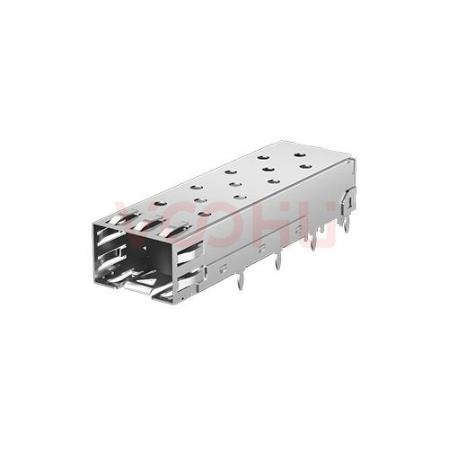
Amphenol U77-A1118-200T Alternative: VOOHU WHSFP00111W058 Comparison
Looking to replace an Amphenol U77-A1118-200T? The VOOHU WHSFP00111W058 is a functional alternative — verify with samples in your design. Both are single-port (1×1) press-fit SFP cages in copper alloy, rated −40 to +85 °C operating, and the two drawings print the same front-panel cut-out (15.25 × 10.40 mm), the same host-board hole sizes and counts (ten Ø1.05, nine Ø0.95 and one Ø0.85 mm) and the same 16.25 mm keep-out width. What needs a decision is how the cage meets your board. The drawings word their board-thickness notes differently, and the press-fit tails reach 2.20 mm (Amphenol) and 2.90 mm (VOOHU) below the seating plane. Check both against the stack-up you actually build.
[Product] WHSFP00111W058
What do the U77-A1118-200T and WHSFP00111W058 drawings print?
Amphenol's figures come from customer drawing P-U77-A1118-XX0X, revision G. Its five sheets cover materials and the part-number key (sheet 1), the outline (2), the bezel cut-out (3), the single-sided host-board layout (4) and the belly-to-belly layout (5). That drawing is dimensioned in inches with millimetres in brackets, and the millimetre values are quoted here. VOOHU's figures come from the WHSFP00111W058 drawing, revision A0: outline, materials and temperature on page 1, panel cut-out and PCB layout on page 2, all in millimetres. "Not stated" marks an item a drawing leaves out.
| Parameter | Amphenol U77-A1118-200T (source) | VOOHU WHSFP00111W058 (source) |
|---|---|---|
| Type | SFP single cage, 8 press-fit and 12 EMI pins (sheet 1 title) | SFP 1×1 cage, press-fit (p1 title block) |
| Cage material | Copper alloy (sheet 1) | Copper alloy, top and bottom cage (p1, note 1) |
| Plating | Option 2, the "2" in -200T: 100 µin [2.54 µm] min nickel, not for solder pins (sheet 1) | Nickel, "Ni for all" (title block); thickness not stated |
| Operating temperature | −40 to +85 °C (sheet 1) | −40 to +85 °C; storage −55 to +105 °C (p1, note 3) |
| Length | 48.98 (sheet 2) | 48.73 ± 0.07 (p1) |
| Front width | 14.00 ± 0.10; inside or outside not marked (sheet 2) | 14.00 ± 0.10, marked inside of cage (p1) |
| Front height | 8.95 ± 0.15 (sheet 2) | 8.90 +0.20/−0.10, inside of cage (p1) |
| Side-view height | 10.85, reference (sheet 2) | 10.80 ± 0.35 (p1) |
| Press-fit section width | 1.30 typ (sheet 2) | 1.24 ± 0.05 (p1) |
| Tail length below seating plane | 2.20 (sheet 2) | 2.90 (p1) |
| Front edge to first pin | 11.50 (sheet 2) | 11.50; 5.00 typ between pins (p1) |
| Panel cut-out | 15.25 ± 0.10 × 10.40 ± 0.10; port pitch 16.25; panel 1.70 ± 0.90; 3.50 ± 0.30; opening 0.40 ± 0.10 below PCB (sheet 3) | 15.25 ± 0.10 × 10.40 ± 0.10; port pitch 16.25 min; panel 1.7 ± 0.90; 3.50 ± 0.30; 0.40 ± 0.10; 4 × 0.3 max at each cut-out (p2) |
| Host-board holes | Ø1.05 ± 0.05 × 10, pads and vias chassis ground; Ø0.95 ± 0.05 × 9, plating optional; Ø0.85 ± 0.05 × 1 (sheet 4) | Ø1.05 ± 0.05 × 10; Ø0.95 ± 0.05 × 9; Ø0.85 ± 0.05 × 1 (p2) |
| Keep-out width / hole columns | 16.25; columns at 14.25 / 11.08 / 8.58 / 5.68 (sheet 4) | 16.25 (15.25 + 1.00); columns at 14.25 / 11.08 / 8.58 / 5.68 (p2) |
| Board thickness | Single-sided: 1.45 min, 1.57 nominal; belly-to-belly: 3.00 min (sheets 3–5) | Layout note "PCB thickness: 3.00", no minimum stated; single-sided layout only (p2) |
Board thickness and tail length: why they have to be read together
With a press-fit cage, the board is half of the joint. The compliant sections of the pins are held by being squeezed inside the plated holes, and the tails either stop inside the board or come out underneath, depending on its thickness. The two drawings describe that relationship in different terms. Amphenol states minimums: 1.45 mm (1.57 mm nominal) for a cage on one side of the board, and 3.00 mm where cages are mounted belly-to-belly on both sides. The VOOHU layout carries one note, "PCB thickness: 3.00", with no minimum, no range and no belly-to-belly layout. The note does not say whether 3.00 mm is a minimum, a nominal or simply the board the layout was drawn on, so read neither a requirement nor a limit into it. Ask instead.
Tail length is the other half. Measured from the seating plane, the Amphenol tails are 2.20 mm long and the VOOHU tails 2.90 mm. Subtract your board thickness from each: a positive result is how far the tails stand out below the board, and a negative one means they finish inside the hole. Three things depend on that number. Bottom-side components and any copper or label under the cage need the clearance. The support plate your EMS puts under the board during pressing needs relief pockets deep enough for the longer tails, otherwise the pins land on the plate. And on first articles, a cross-section through one hole shows where the compliant section ends up in the barrel. Send your board thickness and mounting style with the sample request, and press samples into your own production board rather than a test coupon of a different thickness.
SFP cage press fit: what changes for the EMS line
Both drawings call for the same three hole sizes at ±0.05 mm. The pins going into them are drawn differently: the width across the press-fit section is 1.30 mm typical on the Amphenol drawing and 1.24 ± 0.05 mm on the VOOHU drawing. A different pin width in the same hole is a different interference, so the press force your line settled on for the U77-A1118-200T is not a value to carry over. Run a force-versus-travel check on first articles and look at the hole walls in the cross-section. Amphenol also notes that the pads and vias around the cage are chassis ground and that plating is optional on its nine Ø0.95 mm holes. The VOOHU drawing carries no plating notes for the holes, so if your board leaves those holes unplated, confirm with our FAE team that this suits the WHSFP00111W058. One last point for the repair bench: Amphenol marks its nickel option as not for solder pins, which means the cage is meant to be pressed, not soldered. Agree a rework method for the replacement part in writing before you need it.
Plating, units and inside dimensions on the incoming inspection sheet
Three things catch out an inspection sheet carried over from the Amphenol part. First, plating: option 2 on the Amphenol drawing is 100 µin (2.54 µm) minimum nickel, while the VOOHU drawing specifies nickel without a thickness. If your specification or an environmental test plan calls for a thickness, ask VOOHU for a written figure or a plating-thickness report before approval, and enter the number you receive rather than the Amphenol one. Second, units: the Amphenol drawing is dimensioned in inches with millimetres in brackets, so convert tolerances with care when you rebuild the sheet from the VOOHU drawing, which is in millimetres. Third, the reference for the front-end dimensions. VOOHU marks its 14.00 mm width and 8.90 mm height as inside of the cage, while the Amphenol drawing does not say whether its 14.00 × 8.95 mm is inside or outside. Gauge the opening from the inside on VOOHU lots, because a caliper reading across the outside of the shell will not compare with that figure. The length differs as well, 48.98 against 48.73 mm, which deserves a look where a heat sink or a component sits right behind the cage.
Press in, gauge, approve: what each team checks before the WHSFP00111W058 goes on the BOM
Layout and mechanical
- Send your board thickness and mounting style (single-sided or belly-to-belly) with the sample request, and ask our FAE team how the "PCB thickness: 3.00" note applies to your board.
- Work out tail protrusion (2.90 mm minus board thickness) and check clearance to bottom-side parts.
- Overlay the VOOHU hole layout on your current SFP cage footprint; the hole sizes and the dimensioned rows and columns should line up.
- Check rear clearance for the 48.73 mm length, and offer a sample cage up to your existing 15.25 × 10.40 mm panel cut-out.
EMS and press-fit
- Confirm the support-plate relief pockets are deeper than the tail protrusion worked out above (2.90 mm minus board thickness).
- Set press force from a first-article force-versus-travel curve for the 1.24 mm press-fit section, and cross-section one hole.
- Agree the rework method for the WHSFP00111W058 in writing.
Quality and incoming inspection
- Obtain a written nickel thickness or a plating report if your specification needs one.
- Rebuild dimension checks in millimetres from the VOOHU drawing, and gauge 14.00 × 8.90 mm on the inside of the cage.
- List the WHSFP00111W058 as a functional alternative pending sample approval.
Where a single press-fit SFP cage like this goes
Any board with one SFP port that is assembled by soldering the other parts first and pressing the cage in afterwards, where the panel opening is already cut to 15.25 × 10.40 mm and the product operates within −40 to +85 °C. Typical examples are the SFP uplink on a managed switch, the fibre WAN port on an enterprise router and an SFP slot on a data-communication line card. For multi-port cages, light pipes or SFP+ and SFP28 versions, see our SFP+ and SFP28 cage selection guide and the overview of SFP cages and accessories.
[Solution] /data-communication/
FAQ
Q1: Is there a replacement for the Amphenol U77-A1118-200T SFP cage?
VOOHU's WHSFP00111W058 is a functional alternative to the Amphenol U77-A1118-200T — verify with samples in your design. It is a 1×1 press-fit SFP cage rated −40 to +85 °C, and its drawing gives the same panel cut-out, host-board hole sizes and counts and 16.25 mm keep-out width as the Amphenol drawing. Confirm board thickness and the 2.90 mm tail length against your own stack-up.
Q2: What is the difference between U77-A1118-100T and U77-A1118-200T?
On Amphenol's drawing P-U77-A1118-XX0X, the first digit of the -XX0X suffix selects the plating option. "2" is option 2: 100 µin (2.54 µm) minimum nickel, marked not for solder pins. Option 1 is a different finish defined on sheet 1 of the same drawing, so check that sheet before treating the two part numbers as interchangeable on a BOM.
Q3: What PCB thickness does a press-fit SFP cage need?
It depends on the cage, so take it from each drawing. For the U77-A1118, Amphenol gives 1.45 mm minimum (1.57 mm nominal) for single-sided mounting and 3.00 mm minimum for belly-to-belly mounting. The WHSFP00111W058 layout carries the note "PCB thickness: 3.00" without a minimum; ask our FAE team how it applies to your board before you build.
Q4: Is the U77-A1118-200T press-fit or solder?
Press-fit. Amphenol's drawing titles it an SFP single cage with 8 press-fit and 12 EMI pins, and its nickel plating option is marked not for solder pins. If a parts listing shows a solder termination, go by the drawing. The WHSFP00111W058 is a press-fit cage as well.
Send your stack-up and press-fit setup with the sample request
Use the WHSFP00111W058 sample request and include your board thickness, whether cages sit on one side or both, and the support-plate design your EMS uses for pressing. Samples are available for evaluation, and selected parts are free of charge. Our FAE team will be glad to confirm the options for your project. Our FAE team can suggest suitable parts and help check the design — for this pair, how the 3.00 mm thickness note and the 2.90 mm tails sit on your stack-up, how the press-fit holes should be finished, and the nickel thickness figure your inspection sheet needs.
VOOHU supplies RJ45 and SFP connectors, LAN and PoE transformers and common mode chokes from Suzhou, China, to more than 1,500 customers.
Looking at other press-fit SFP cages, including multi-port versions? The SFP connector selector opens filtered to press-fit SFP cages.
Related product: WHSFP00111W058 — 1×1 press-fit SFP cage, copper alloy with nickel plating, −40 to +85 °C operating.