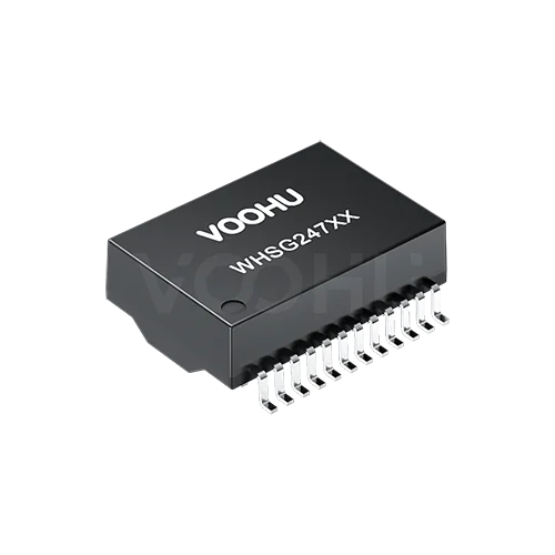
HanRun HY682405 Alternative: VOOHU WHSG24701G Comparison
The HanRun HY682405 is 0.130 in (about 3.30 mm, converted) tall at most, and the VOOHU WHSG24701G is 6.00 ± 0.50 mm. Consider the swap only where at least 6.50 mm of vertical clearance exists above the transformer. Where that space exists, the WHSG24701G is a functional alternative to the HY682405 — verify with samples in your design. Both are single-port 100/1000BASE-T LAN transformers with 24 SMD leads on a 1.27 mm pitch and a 16.00 mm span across the leads, both are rated 0 to +70 °C, and both schematics give every pin the same signal name and every channel the same 1CT:1CT transformer and two-wire choke. Two further differences: the recommended pads, with inner and outer edges 12.19 / 16.76 mm apart on the HanRun drawing (converted) against 12.70 / 16.60 mm, and the hipot leakage criterion, 0.5 mA against 1 mA at 1500 V for 60 s.
[Product] WHSG24701G
The HY682405 datasheet next to the WHSG24701G datasheet
The HanRun column is read from the HY682405 datasheet, REV A/4 (distributor-hosted): one page covering the electrical table, schematic, outline and recommended pads, dimensioned in inches. The millimetre figures in brackets are converted from those inches, and three-place inch dimensions without their own tolerance fall under the drawing's general ± 0.010 in. The VOOHU column comes from the WHSG24701G datasheet, revision A0, dimensioned in millimetres, with the outline, recommended pads and schematic on page 1 and the electrical items on page 2. Not stated means the document gives no value; calculated means the figure is worked out from printed dimensions.
| Parameter | HanRun HY682405 (datasheet REV A/4, distributor-hosted) | VOOHU WHSG24701G (datasheet A0) |
|---|---|---|
| Document title / data rate | 100/1000Base-T Magnetics Modules | 100/1000 BASE-T (p1 title block) |
| Channels and structure | 4 channels; each a 1CT:1CT transformer, a two-wire common mode choke on the line side, line-side center tap brought straight out to MCT | 4 channels; each a 1CT:1CT transformer, a two-wire common mode choke on the line side, line-side center tap brought straight out to MCT (p1) |
| Chip-side pins | TCT1 1, TD1+ 2, TD1− 3 through TCT4 10, TD4+ 11, TD4− 12 | TCT1 1, TD1+ 2, TD1− 3 through TCT4 10, TD4+ 11, TD4− 12 (p1) |
| Line-side pins | MCT1 24, MX1+ 23, MX1− 22 through MCT4 15, MX4+ 14, MX4− 13 | MCT1 24, MX1+ 23, MX1− 22 through MCT4 15, MX4+ 14, MX4− 13 (p1) |
| Leads / pitch / first to last lead | 24 / 0.050 in (1.27) / 0.550 in (13.97) | 24 / 1.27 ± 0.20 / 13.97 ± 0.20 (p1) |
| Body length | 0.700 ± 0.015 in (17.78 ± 0.38) | 17.55 ± 0.50 (p1) |
| Body width | 0.480 ± 0.015 in (12.19 ± 0.38) | 12.20 ± 0.50 (p1) |
| Width across leads | 0.630 in (16.00) | 16.00 ± 0.50 (p1) |
| Height | 0.130 in (3.30) max | 6.00 ± 0.50 (p1); 5.50 to 6.50, calculated from the tolerance |
| Lead width / foot length | 0.020 ± 0.005 in (0.51 ± 0.13) / 0.035 in (0.89) | 0.50 ± 0.10 / 1.10 ± 0.15 (p1) |
| Standoff | Not stated | 0.25 ± 0.15 (p1) |
| Recommended pad width / pitch / first to last pad | 0.030 in (0.76) / 0.050 in (1.27) / 0.550 in (13.97) | 0.76 typ / 1.27 typ / 13.97 typ (p1) |
| Recommended pads: inner / outer edges | 0.480 in (12.19) / 0.660 in (16.76) | 12.70 typ / 16.60 typ (p1) |
| Pad length | 2.29 (0.090 in), calculated from the edges | 1.95, calculated from the edges |
| OCL | Not stated | 350 µH min at 100 kHz, 0.1 V, 8 mA DC bias (p2) |
| Leakage inductance / DCR | Not stated | 0.5 µH max / 1400 mΩ max (p2) |
| Turns ratio | 1CT:1CT (schematic); tolerance not stated | 1CT:1CT ± 5% (p2) |
| Insertion loss | −1.0 dB max, 1–100 MHz | −1.1 dB max, 1–100 MHz (p2) |
| Return loss | −16 dB min, 1–40 MHz; −12 dB, 60–80 MHz; −10 dB at 100 MHz; 40–60 MHz not stated | −18 dB, 1–30 MHz; −14.4 dB at 40 MHz; −13.1 dB at 50 MHz; −12 dB, 60–80 MHz; −10 dB at 100 MHz (p2) |
| Crosstalk | −40 dB min, 100 kHz–60 MHz; −33 dB min, 60–100 MHz | −30 dB min, 1–100 MHz (p2) |
| Differential to common mode rejection | −43 dB at 30 MHz; −37 dB at 60 MHz; −33 dB at 100 MHz | Not stated |
| Common mode rejection | Not stated | −30 dB min, 1–100 MHz (p2) |
| Isolation (hipot) | 1500 Vrms, 0.5 mA, 60 s, primary to secondary | 1500 VAC, 1 mA, 60 s; point of application not stated (p2) |
| Operating temperature | 0 to +70 °C | 0 to +70 °C (p2) |
| Storage temperature | Not stated | −40 to +85 °C (p2) |
HY682405 height against WHSG24701G height: measure the clearance first
These two heights are not a tolerance question. HanRun caps the HY682405 at 0.130 in, which converts to 3.30 mm. VOOHU draws the WHSG24701G at 6.00 mm ± 0.50 mm, so even the shortest part that drawing allows, 5.50 mm, stands 2.20 mm above the HanRun ceiling, and the nominal height is roughly 1.8 times the HanRun maximum (both calculated). If the HY682405 was chosen because it fits under a low lid or a thin card outline, this is where the substitution stops, and the decision belongs to whoever owns the enclosure model rather than the schematic.
The measurement itself is short. Find the lowest surface over the transformer footprint: the inside of a shield can, an enclosure cover, a heatsink, a board stacked above, or a cable or flex routed across that area. Measure from the top of the PCB to that surface and take off your assembly tolerances. At 6.50 mm or more, the board position can take the WHSG24701G and the next step is the pads. Below 6.50 mm, it cannot, and there is no reason to order samples for that position. Tell us the clearance you have: our FAE team can suggest suitable parts and help check the design.
Can the HY682405 land pattern stay? Inner pad edges 12.19 vs. 12.70 mm
Along each row, the two recommended patterns agree: 0.76 mm wide pads on a 1.27 mm pitch, 13.97 mm from the first pad to the last. Across the rows they part ways. HanRun puts the inner pad edges 12.19 mm apart and the outer edges 16.76 mm apart (converted from 0.480 and 0.660 in); VOOHU recommends 12.70 and 16.60 mm. With both patterns centred on one point, each HanRun pad reaches about 0.25 mm further in toward the body and about 0.08 mm further out, so it is about 2.29 mm long against about 1.95 mm for the VOOHU pad (all calculated from the edge dimensions).
What matters is where the WHSG24701G foot lands. With a 16.00 mm span across the leads and a 1.10 mm foot, the inner ends of its feet sit about 13.80 mm apart (calculated), which is on the pad in both patterns. The extra HanRun copper is on the body side, under the part, where the joint cannot be seen from above. So on a board already built with HanRun pads, the open questions are paste volume and whether solder beads or bridges form under the body, and a first-article build is what answers them. Look at pins 1, 12, 13 and 24 and a few middle pins from the side, and use X-ray if you have it. If beads show up, one option to discuss with your EMS before any copper change is a stencil aperture reduced toward the VOOHU pad length. For a new layout, draw the VOOHU pattern. Using the WHSG24701G on HanRun pads has not been confirmed in writing by our FAE team so far.
Hipot leakage current limit and the other lines on your inspection sheet
An incoming or production hipot test written around the HY682405 applies 1500 V for 60 s from primary to secondary and fails any part that leaks more than 0.5 mA. The WHSG24701G datasheet keeps the voltage and the time but sets the criterion at 1 mA, and it does not say where the voltage is applied. That is a different pass definition, not a different test result. Write the WHSG24701G line from its own datasheet, 1500 VAC, 1 mA, 60 s, and confirm the application point with us. If a customer specification or a safety file holds you to 0.5 mA, ask us for written data at that limit before you change the tester setting, and log voltage, time and trip current with every result so it is clear which limit a lot was released against. The wider isolation path is covered in our article on why an Ethernet port fails the Hi-Pot test.
Then work down the electrical lines. Insertion loss is −1.0 dB maximum on the HanRun sheet and −1.1 dB maximum on the VOOHU sheet, both from 1 to 100 MHz, so the WHSG24701G line takes −1.1 dB. Return loss and crosstalk are split into different frequency bands on the two sheets, and HanRun leaves 40 to 60 MHz out of its return loss, so copy the VOOHU bands as written rather than mapping one set onto the other. HanRun lists differential to common mode rejection and VOOHU lists common mode rejection; the names differ and neither sheet gives a method or fixture, so keep them as two lines and do not compare them. Every one of these is a datasheet limit, not a measurement of any lot, and your own link and EMC tests are where the board is judged. One more gap to note: the HanRun electrical table has seven items, and open circuit inductance, leakage inductance and DCR are not among them. If your approval document carries an OCL line for the HY682405, it came from somewhere other than this datasheet. For the WHSG24701G, the datasheet gives 350 µH minimum at 100 kHz, 0.1 V with 8 mA DC bias; to compare like with like, measure one HY682405 and your WHSG24701G samples under that condition on the same bridge.
HY682405 to WHSG24701G: a nine-step swap checklist
| # | Step | Owner | Pass condition |
|---|---|---|---|
| 1 | Measure from the PCB top to the lowest surface over the transformer, minus assembly tolerances | Mechanical | 6.50 mm or more; otherwise stop here |
| 2 | Give the library part a 6.00 ± 0.50 mm body and rerun the interference check at 6.50 mm | Mechanical / CAD | No interference at 6.50 mm |
| 3 | Overlay the HanRun and VOOHU pad patterns on the existing board | Layout | Inner foot ends (about 13.80 mm apart, calculated) on copper |
| 4 | First article on the existing pads: pins 1, 12, 13, 24 and middle pins, side view and X-ray | EMS / Layout | No beads or bridges under the body; any stencil change recorded |
| 5 | Hipot set to 1500 VAC, 1 mA, 60 s, application point confirmed, or written VOOHU data for a 0.5 mA limit | Incoming inspection | Setting logged with every result |
| 6 | Insertion loss −1.1 dB max; return loss and crosstalk bands copied from the VOOHU sheet; common mode lines kept separate | Incoming inspection / component engineering | Inspection sheet revised |
| 7 | OCL on samples at 100 kHz, 0.1 V, 8 mA DC bias; one HY682405 on the same bridge if you want a reference | Component engineering | 350 µH min |
| 8 | Height inspected against 6.00 ± 0.50 mm | Incoming inspection | Sample lot inside the drawing range |
| 9 | Alternate entry written with its condition: positions with at least 6.50 mm of clearance only | Purchasing / component engineering | Approved list entry carries the clearance condition |
Where the WHSG24701G fits, and where it does not
The WHSG24701G suits a single 100/1000BASE-T port laid out for a 24-lead, 1.27 mm-pitch SMD transformer in equipment rated 0 to +70 °C, where the transformer sits in open board area with 6.50 mm or more above it. It is the wrong choice for a position under a low shield, a thin card outline or a closely stacked board, positions that may need a part no taller than 3.30 mm. Other HanRun parts and their VOOHU counterparts are listed in our HanRun cross reference.
[Solution] /solution-ethernet/
FAQ
Q1: What is an alternative to HanRun HY682405?
Where at least 6.50 mm of vertical clearance is available, the VOOHU WHSG24701G is a functional alternative to the HanRun HY682405 — verify with samples in your design. Both are single-port 100/1000BASE-T LAN transformers with 24 SMD leads on a 1.27 mm pitch, a 16.00 mm lead span, the same signal name on every pin and 0 to +70 °C ratings. The HY682405 is 0.130 in (3.30 mm, converted) maximum and the WHSG24701G is 6.00 ± 0.50 mm tall.
Q2: How tall is the HY682405 compared with the WHSG24701G?
The HanRun drawing gives the HY682405 a maximum height of 0.130 in, about 3.30 mm when converted. The VOOHU drawing gives the WHSG24701G 6.00 ± 0.50 mm, a range of 5.50 to 6.50 mm (calculated). Check that the space above the transformer takes 6.50 mm before you plan the swap.
Q3: What is the hipot leakage current limit for the HY682405 and the WHSG24701G?
Each datasheet sets its own limit at 1500 V for 60 s. The HY682405 datasheet uses 0.5 mA, primary to secondary; the WHSG24701G datasheet uses 1 mA and does not state the application point. Set the tester to the limit of the part under test, and ask VOOHU for written data if your specification requires 0.5 mA on the WHSG24701G.
Q4: Does the HY682405 datasheet give the transformer open circuit inductance?
No. The HY682405 datasheet (REV A/4, distributor-hosted) lists no OCL, leakage inductance or DCR; its schematic shows a 1CT:1CT ratio without a tolerance. The WHSG24701G datasheet gives 350 µH minimum OCL at 100 kHz, 0.1 V with 8 mA DC bias, 0.5 µH maximum leakage inductance and 1400 mΩ maximum DCR. For a direct comparison, measure both parts under the same condition.
Q5: Can the WHSG24701G be soldered onto an existing HY682405 footprint?
Plan it as a first-article trial. Pad width, 1.27 mm pitch and the 13.97 mm row length are the same in both recommended patterns, but the HanRun pads run from 12.19 to 16.76 mm across the rows (converted) and the VOOHU pads from 12.70 to 16.60 mm. The WHSG24701G feet land on the HanRun pads (calculated); check under the body for solder beads or bridges. Using the WHSG24701G on HanRun pads has not been confirmed in writing by our FAE team so far.
What to send with a WHSG24701G sample request
Measure first, then request WHSG24701G samples with three things: the clearance you measured above the transformer, the pad dimensions on your current HY682405 board, and the hipot settings on your inspection sheet. Samples are available for evaluation, and selected parts are free of charge. Our FAE team will be glad to confirm the options for your project. Our FAE team can suggest suitable parts and help check the design — for this pair, whether 6.00 ± 0.50 mm fits your enclosure, how the feet sit on your HanRun pads, and which hipot limit and application point to write down.
VOOHU supplies RJ45 and SFP connectors, LAN and PoE transformers and common mode chokes from Suzhou, China, to more than 1,500 customers.
To compare other 24-pin, 1.27 mm-pitch parts, open the LAN transformer selector with the pin count and pitch already filtered.
Related product: the WHSG24701G, a 100/1000BASE-T single-port LAN transformer in a 24-lead SMD package with a 1.27 mm pitch, a 17.55 × 12.20 mm body and a height of 6.00 ± 0.50 mm. Each of its four channels pairs a 1CT:1CT transformer with a two-wire common mode choke on the line side. The datasheet lists 350 µH minimum OCL with 8 mA DC bias, a 1500 VAC, 60 s hipot test and a 0 to +70 °C operating range.