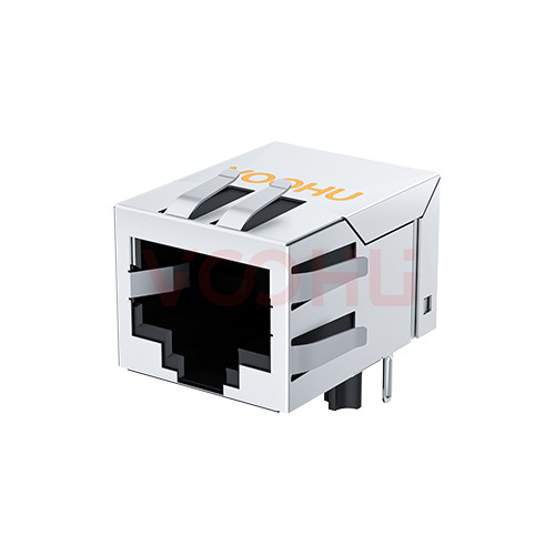
LINK-PP LPJ4011CNL Alternative: VOOHU SYT111B002HWA1D Comparison
A board drilled for the LINK-PP LPJ4011CNL already has a hole at every position the VOOHU SYT111B002HWA1D uses: the eight signal holes, two shield-pin holes and two locating-post holes line up hole by hole on the printed dimensions of the two drawings. The SYT111B002HWA1D is a functional alternative to the LPJ4011CNL — verify with samples in your design. Both are 1×1 tab-down 10/100 RJ45 jacks with integrated magnetics (MagJack), without LEDs, with 1CT:1CT ± 2% windings, 350 µH minimum OCL and a −40 to +85 °C operating range. What differs sits inside the holes. The shield-pin holes are Ø1.70 mm on the LINK-PP drawing and Ø1.63 mm on the VOOHU drawing, and the signal pins are drawn 4.0 ± 0.5 mm long on the LPJ4011CNL against 3.6 mm on the SYT111B002HWA1D.
[Product] SYT111B002HWA1D
LPJ4011CNL vs. SYT111B002HWA1D: datasheet values side by side
LINK-PP publishes the LPJ4011CNL as a two-sheet drawing, LP07113006 revision A, dated 30 November 2007: the schematic and electrical table on sheet 1, the outline and recommended PCB layout on sheet 2. VOOHU's SYT111B002HWA1D datasheet, revision A0, runs to four pages: outline and hole layout on page 1, the panel cut-out and a component-side keep-out area on page 2, schematic and electrical table on page 3, wave-soldering conditions on page 4. All dimensions are in millimetres on both. A cell reading "not stated" means that datasheet prints nothing for the line.
| Parameter | LINK-PP LPJ4011CNL (source) | VOOHU SYT111B002HWA1D (source) |
|---|---|---|
| Data rate | 10/100 Base-T (drawing title) | 10/100BASE (DS title block) |
| Ports / tab | 1×1, tab down (sheet 2 front view) | 1×1, tab down (DS title block) |
| LEDs | None (sheet 1–2) | None (DS p1, p3) |
| EMI fingers | Drawn on the front view (sheet 2) | Drawn on the front view (DS p1) |
| Pin functions | TD+ 1, TD− 2, RD+ 3, CT 4, CT 5, RD− 6, NC 7, GND 8 (sheet 1) | TD+ 1, TD− 2, RD+ 3, CT 4, CT 5, RD− 6, GND 8 (DS p3) |
| Circuit | Transformer with line-side common mode choke; 75 Ω × 4 and 1000 pF, 2 kV termination (sheet 1) | Transformer with line-side common mode choke; 75 Ω × 4 and 1000 pF, 2 kV termination (DS p3) |
| Turns ratio | 1CT:1CT ± 2% (sheet 1) | 1CT:1CT ± 2% (DS p3, electrical table) |
| OCL | 350 µH min at 100 kHz, 0.1 V, 8 mA DC (sheet 1) | 350 µH min at 100 kHz, 100 mV, 8 mA DC (DS p3) |
| Insertion loss | −1.0 dB max, 1.0–65 MHz (sheet 1) | −1.0 dB max, 1–100 MHz (DS p3) |
| Return loss, min | −20 dB 1–10 MHz; −16 dB 10–30 MHz; −12 dB 30–60 MHz; −10 dB 60–100 MHz (sheet 1) | −20 dB 1–10 MHz; −16 dB 10–30 MHz; −12 dB 30–60 MHz; −10 dB 60–80 MHz (DS p3) |
| Crosstalk, min | −40 dB 1–30 MHz; −35 dB 30–60 MHz; −30 dB 60–100 MHz (sheet 1) | −40 dB 1–30 MHz; −35 dB 30–60 MHz; −30 dB 60–100 MHz (DS p3) |
| Common mode rejection, min | −30 dB 1–50 MHz; −20 dB 50–150 MHz (sheet 1) | −30 dB 1–100 MHz (DS p3) |
| Hipot | 1500 Vrms min; test time and leakage current not stated (sheet 1) | 1500 V AC and 2250 V DC, 6 s, 1 mA, primary to secondary (DS p3) |
| Operating temperature | −40 to +85 °C (sheet 1) | −40 to +85 °C (DS p1) |
| Storage temperature | Not stated | −40 to +85 °C (DS p1) |
| Outline, W × H × D | 15.90 × 13.40 × 21.30 mm, general tolerance ±0.20 (sheet 2) | 16.00 × 13.45 × 21.10 mm, general tolerance ±0.25 (DS p1) |
| Signal holes | Ø0.90 × 8; 1.27 mm stagger, 2.54 mm between rows, 8.89 mm pin 1 to pin 8 (sheet 2) | Ø0.89 × 8; 1.27 mm, 2.54 mm, 8.89 mm (DS p1) |
| Shield-pin holes | Ø1.70 × 2; 15.75 mm apart, 3.05 mm from the post line (sheet 2) | Ø1.63 × 2; 15.75 mm, 3.05 mm (DS p1) |
| Locating-post holes | Ø3.20 × 2, 11.43 mm apart (sheet 2) | Ø3.20 × 2, 11.43 mm (DS p1) |
| Rear signal row to post line | 8.89 mm (sheet 2) | 8.89 mm (DS p1) |
| Front face to post line | 10.80 mm (sheet 2) | 10.75 mm (DS p1) |
| Signal pin length below the seating plane | 4.0 ± 0.5 mm (sheet 2) | 3.6 mm, general tolerance ±0.30 (DS p1) |
| Shield pin / locating post length | Not stated | 3.65 mm / 3.20 mm (DS p1) |
| Panel cut-out | Not stated | 16.15 × 13.75 mm, reference only (DS p2) |
| Component-side keep-out area | Not stated | Dimensioned (DS p2) |
| Durability / mating force | Not stated | 750 cycles min / 23 N max (DS p1) |
| Wave soldering | 265 °C max, 5 s max (sheet 2, note 4) | 260 ± 5 °C, 5 s max (DS p4) |
RJ45 hole size and footprint: what lines up on the LPJ4011CNL board
A position comparison needs one reference on both drawings. Here it is the line through the centres of the two locating posts, together with the left–right centreline of the jack. Against that reference the two layouts agree hole by hole. In the top view, with the jack opening at the bottom of the view, both put pins 2, 4, 6 and 8 in the rear row and pins 1, 3, 5 and 7 in the front row, with pin 1 at the left; the rows are staggered by 1.27 mm, sit 2.54 mm apart and are centred on the centreline. The rear row is 8.89 mm from the post line. The two shield pins sit 3.05 mm from the post line and 15.75 mm apart, and the posts are 11.43 mm apart. On a board drilled to the LINK-PP layout, no hole position has to move; whether the existing hole sizes suit the VOOHU pins is the next question.
The diameters are another matter, and they are where the Layout engineer should spend the review. LINK-PP recommends Ø1.70 mm for the two shield-pin holes; VOOHU recommends Ø1.63 mm, so a board drilled for the LPJ4011CNL is 0.07 mm larger in diameter there than the VOOHU drawing asks for, about 0.035 mm per side (calculated). The signal holes are Ø0.90 against Ø0.89 mm. Neither drawing gives the cross-section of the shield pins, so the gap around them cannot be worked out on paper; it has to be seen in a soldered joint. Before comparing numbers, check whether your fabrication drawing calls out drilled or finished hole sizes, because that decides which figure you are holding against each datasheet. Two items exist only on the VOOHU side: a component-side keep-out area and a reference panel cut-out of 16.15 × 13.75 mm on page 2. Lay the keep-out over the copper and parts around the jack on your existing board. The front face also sits 10.75 mm from the post line instead of 10.80 mm, so it ends 0.05 mm closer to the posts at the panel (calculated).
Lead protrusion when the signal pin is 3.6 mm instead of 4.0 mm
For the EMS or process engineer, pin length is the number that moves. LINK-PP draws its signal pins 4.0 ± 0.5 mm below the seating plane, so 3.5 to 4.5 mm; VOOHU draws them 3.6 mm under its general tolerance of ±0.30 mm, so 3.30 to 3.90 mm (ranges calculated). The VOOHU nominal falls inside the LINK-PP tolerance, toward its lower end. VOOHU also dimensions the shield pins at 3.65 mm and the locating posts at 3.20 mm; the LINK-PP drawing gives neither. With the jack seated flat, protrusion is pin length minus board thickness. On a 1.6 mm board that is 2.0 mm nominal for the VOOHU signal pins and 2.4 mm for the LINK-PP, or 1.70–2.30 mm against 1.9–2.9 mm across tolerance; on a 2.4 mm board the nominal figures are 1.2 and 1.6 mm (all calculated). Run the numbers for your own board thickness, compare them with the protrusion your workmanship standard requires, and look at the solder side of the first boards: pin tips visible, hole fill in the two shield holes as well as the signal holes, and any test fixture or AOI program that assumed the longer pin. The soldering windows sit close together: 265 °C maximum for 5 s on the LINK-PP note, 260 ± 5 °C for 5 s maximum on the VOOHU sheet, so the upper ends agree at 265 °C (calculated).
Hipot terms and electrical bands to carry into incoming inspection
Quality teams will find the isolation lines written to different depths. The LPJ4011CNL drawing says 1500 Vrms minimum and stops there, with no test time and no leakage limit. The SYT111B002HWA1D datasheet states 1500 V AC and 2250 V DC for 6 s at 1 mA, primary to secondary. Write the incoming inspection line for the VOOHU part from those terms. If a customer file or safety report fixes a different test time, ask us for data under that condition; the LINK-PP line has no duration that could be carried over. For the component engineer, turns ratio, OCL and all three crosstalk bands read alike on both tables. Three bands are drawn differently. Insertion loss is −1.0 dB maximum to 65 MHz on the LINK-PP sheet and to 100 MHz on the VOOHU sheet. The last return loss step, −10 dB minimum, runs to 100 MHz on LINK-PP and to 80 MHz on VOOHU. Common mode rejection is −30 dB minimum to 50 MHz plus −20 dB minimum from 50 to 150 MHz on LINK-PP, against −30 dB minimum from 1 to 100 MHz on VOOHU. If your design review quotes return loss between 80 and 100 MHz or common mode rejection between 100 and 150 MHz, mark those lines not stated for the VOOHU part and ask us for data.
LPJ4011CNL to SYT111B002HWA1D: swap checklist
| # | Check | Who | Reference |
|---|---|---|---|
| 1 | Overlay the VOOHU hole layout on the board: 8 signal, 2 shield-pin and 2 post holes from the post-line reference | Layout | VOOHU DS p1 |
| 2 | Note shield holes Ø1.70 (board) against Ø1.63 mm (VOOHU) and signal holes Ø0.90 against Ø0.89 mm; confirm drilled or finished sizes on the fab drawing | Layout | Your fabrication drawing |
| 3 | Lay the VOOHU component-side keep-out area over copper and parts near the jack | Layout | VOOHU DS p2 |
| 4 | Calculate protrusion for your board thickness: signal 3.6 mm (±0.30 general tolerance), shield 3.65 mm, post 3.20 mm | EMS / process | Your workmanship standard |
| 5 | First-article wave solder: hole fill in shield and signal holes, pin tips on the solder side, test fixture and AOI positions | EMS | 260 ± 5 °C, 5 s max (VOOHU DS p4) |
| 6 | Write hipot as 1500 V AC / 2250 V DC, 6 s, 1 mA, primary to secondary; ask us for data if your file names another test time | Quality | VOOHU DS p3 |
| 7 | Mark return loss 80–100 MHz and common mode rejection 100–150 MHz not stated for VOOHU; insertion loss is now specified to 100 MHz | Component engineer | VOOHU DS p3 |
| 8 | Check the panel opening against the 16.15 × 13.75 mm reference cut-out and the 16.00 × 13.45 mm body | Mechanical | VOOHU DS p1–p2 |
Where the SYT111B002HWA1D fits
The SYT111B002HWA1D is one tab-down 10/100 port with the magnetics inside the jack, no status LEDs and EMI fingers toward the panel, rated −40 to +85 °C. That suits equipment that reports link state somewhere other than the connector, or not at all: industrial controllers and I/O modules, sensors and gateways with a single copper port. If your board began on a Pulse JX0011D21NL instead, our JX0011D21NL comparison covers that drawing.
[Solution] /solution-ethernet/
FAQ
Q1: What is an equivalent for the LINK-PP LPJ4011CNL RJ45 jack without LEDs?
The VOOHU SYT111B002HWA1D is a functional alternative to the LINK-PP LPJ4011CNL — verify with samples in your design. Both are 1×1 tab-down 10/100 RJ45 jacks with integrated magnetics and no LEDs, with 1CT:1CT ± 2% windings, 350 µH minimum OCL and −40 to +85 °C operation. Their hole positions line up on the printed dimensions of both drawings; the shield-pin holes (Ø1.70 against Ø1.63 mm) and signal pin length (4.0 ± 0.5 against 3.6 mm) differ.
Q2: What RJ45 hole sizes does the LPJ4011CNL footprint use, and which change for the SYT111B002HWA1D?
The LPJ4011CNL drawing recommends Ø0.90 mm for the eight signal holes, Ø1.70 mm for the two shield pins and Ø3.20 mm for the two locating posts. The SYT111B002HWA1D drawing gives Ø0.89, Ø1.63 and Ø3.20 mm at those positions. The shield-pin hole is the one to review: on an existing LINK-PP board, check solder fill there on first-article boards; on a new layout, use the VOOHU sizes.
Q3: How much lead protrusion will the SYT111B002HWA1D have on my board?
Subtract your board thickness from the pin length below the seating plane. The VOOHU signal pin is 3.6 mm with a general tolerance of ±0.30 mm, so on a 1.6 mm board it protrudes 2.0 mm nominal, 1.70 to 2.30 mm across tolerance; the LPJ4011CNL pin, 4.0 ± 0.5 mm, gives 2.4 mm nominal (calculated). Shield pins are 3.65 mm and locating posts 3.20 mm on the VOOHU drawing. Compare the result with your workmanship standard.
Q4: Hipot test duration: what do the LPJ4011CNL and SYT111B002HWA1D datasheets state?
The LPJ4011CNL drawing gives 1500 Vrms minimum without a test time or leakage current. The SYT111B002HWA1D datasheet gives 1500 V AC and 2250 V DC for 6 s at 1 mA, primary to secondary. Write incoming inspection from the VOOHU terms; if your documentation requires another duration, ask us for data under that condition. Our article on why an Ethernet port fails a hipot test covers the rest of the isolation path.
Q5: RJ45 tab up or down: which are the LPJ4011CNL and SYT111B002HWA1D?
Both are tab down: the latch opening of the jack faces the PCB, and the contacts sit at the top of the port. When you replace one with the other, the cable latch stays on the board side, so panel labelling and cable routing do not change on that account.
Request SYT111B002HWA1D samples for a first-article build
Bring the board, not just the part number. When you request SYT111B002HWA1D samples, tell us the board thickness, the hole sizes on your LPJ4011CNL layout (drilled or finished) and the hipot conditions your incoming inspection uses. Samples are available for evaluation, and selected parts are free of charge. Our FAE team will be glad to confirm the options for your project. Our FAE team can suggest suitable parts and help check the design — for this pair, how the shield pins sit in Ø1.70 mm holes, what protrusion to expect on your board thickness, and which test conditions to write into your inspection plan. VOOHU supplies RJ45 and SFP connectors, LAN and PoE transformers and common mode chokes from Suzhou, China, to more than 1,500 customers.
To compare other 10/100 tab-down parts, with or without LEDs, browse our RJ45 jacks and filter for integrated magnetics.
Related product: SYT111B002HWA1D. A 1×1 tab-down 10/100BASE RJ45 jack with integrated magnetics, no LEDs and EMI fingers, through-hole, 16.00 × 13.45 × 21.10 mm. The datasheet gives 1CT:1CT ± 2% windings, 350 µH minimum OCL at 100 kHz, 100 mV and 8 mA DC, −1.0 dB maximum insertion loss from 1 to 100 MHz, 1500 V AC and 2250 V DC hipot for 6 s at 1 mA, and −40 to +85 °C operating and storage temperature.
Sources
- LINK-PP LPJ4011CNL RJ45 Connector with 10/100 Base-T Integrated Magnetics, drawing LP07113006, Rev. A (2007-11-30), sheets 1–2.
- VOOHU SYT111B002HWA1D datasheet, Rev. A0, pages 1–4.