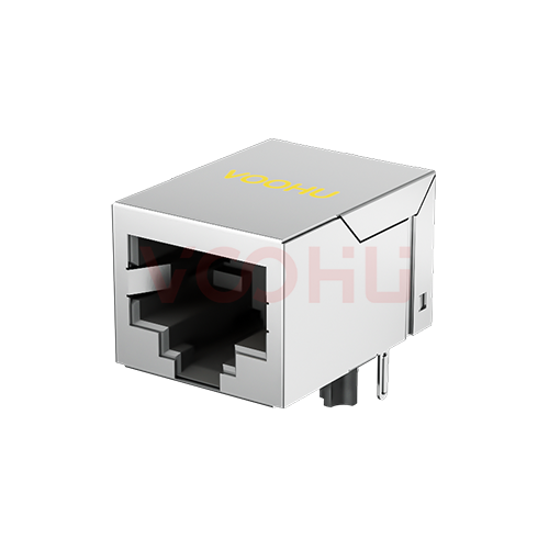
HanRun HR903129A Alternative: VOOHU SYT111B002GWA1D Comparison
For this no-LED jack, the move from the HanRun HR903129A to the VOOHU SYT111B002GWA1D is settled at the front panel and under the connector body more than in the electrical table. The SYT111B002GWA1D is a functional alternative to the HR903129A — verify with samples in your design. Both are single-port, through-hole RJ45 connectors with integrated magnetics for 10/100Base-T, without LEDs, with the same functions on pins 1 to 8 and 350 µH minimum OCL. HanRun suggests a panel cutout of 16.54 × 14.00 mm (± 0.13 mm); VOOHU suggests 16.15 × 13.75 mm and marks it reference only. Of the two datasheets, only the VOOHU one draws a component-side keep-out area under the connector, so parts already placed beneath an HR903129A need checking against it. The operating range is 0 to +85 °C on the HanRun sheet and −40 to +85 °C on the VOOHU sheet.
[Product] SYT111B002GWA1D
What the HR903129A and SYT111B002GWA1D datasheets give
Page numbers in the table refer to two four-page documents. The HanRun HR903129A datasheet, revision 00, a distributor-hosted copy, puts the schematic and electrical data on page 1, the outline on page 2, the PCB layout and suggested panel cutout on page 3, and materials, mechanical ratings and temperature on page 4. The VOOHU SYT111B002GWA1D datasheet, revision A0, puts the outline, hole layout, materials and temperature on page 1, the panel cutout and keep-out area on page 2, and the schematic and electrical table on page 3. All dimensions are in millimetres. Not stated means the datasheet gives no value, and calculated means the figure is worked out from printed dimensions.
| Parameter | HanRun HR903129A (datasheet rev. 00, distributor-hosted) | VOOHU SYT111B002GWA1D (datasheet A0) |
|---|---|---|
| Data rate / ports / LEDs | 10/100Base-T; 1×1; no LEDs (p1, p2 front view) | 10/100BASE; 1×1; tab down; no LEDs (p1; product page) |
| Mounting | Through-hole (p3) | Through-hole, DIP (p1; product page) |
| Pins 1 to 8 | 1 TD+, 2 TD−, 4 transmit center tap, 3 RD+, 6 RD−, 5 receive center tap, 7 not connected, 8 to chassis ground through 1000 pF, 2 kV (p1) | 1 TD+, 2 TD−, 4 CT, 3 RD+, 6 RD−, 5 CT, 7 not connected, 8 GND through 1000 pF, 2 kV (p3) |
| Cable-side termination | Four 75 Ω resistors to the 1000 pF capacitor (p1) | Four 75 Ω resistors to the 1000 pF capacitor (p3) |
| Turns ratio | 1CT:1CT on the schematic; tolerance not stated (p1) | 1CT:1CT ± 2% (p3 electrical table) |
| OCL | 350 µH min at 100 kHz, 100 mV, 8 mA DC (p1) | 350 µH min at 100 kHz, 100 mV, 8 mA DC (p3) |
| Insertion loss | −1.0 dB, 300 kHz–100 MHz (p1) | −1.0 dB, 1–100 MHz (p3) |
| Return loss / crosstalk | Four return loss bands, −20, −16, −12 and −10 dB; three crosstalk bands, −40, −35 and −30 dB (p1) | Same four return loss values and three crosstalk values, in the same frequency bands (p3) |
| Common mode rejection | −30 dB, 1–50 MHz; −20 dB, 50–150 MHz (p1) | −30 dB, 1–100 MHz (p3) |
| Isolation (hipot) | 2250 V DC, 0.5 mA, 60 s (p1) | 1500 V AC and 2250 V DC, 6 s, 1 mA, primary to secondary (p3) |
| Contact plating | 30 µin gold over 50 µin nickel; solder area 100 µin tin over 50 µin nickel (p4) | 6 µin gold on contact area (p1) |
| Housing / shield | PA66 GF; 30 µin nickel over 0.20 mm brass (p4) | PBT; C2680, 0.20 thick, nickel plated (p1) |
| Outline dimensions as drawn | 21.30 × 16.04 × 13.50 (p2) | 21.10 × 16.00 × 13.45 (p1) |
| Signal holes | Ø0.89 × 8 (p3) | Ø0.89 × 8 (p1) |
| Shield-tab holes | Ø1.63 × 2, 15.49 apart (p3) | Ø1.63 × 2, 15.75 apart (p1) |
| Locating-peg holes | Ø3.25 × 2, 11.43 apart (p3) | Ø3.20 × 2, 11.43 apart (p1) |
| Suggested panel cutout | 16.54 ± 0.13 × 14.00 ± 0.13 (p3) | 16.15 × 13.75, ± 0.10, reference only (p2) |
| Dimension drawn at the panel in the cutout side view (not labelled) | 2.03 (p3) | 2.16 (p2) |
| Component-side keep-out area | Not stated | Drawn and dimensioned, ± 0.10 (p2) |
| Mechanical | Mating and unmating 5 lbs max (about 22.2 N, converted); retention 20 lbs min; 750 cycles (p4) | Mating 23 N max; 750 cycles (p1) |
| Operating / storage temperature | 0 to +85 °C / −40 to +85 °C (p4) | −40 to +85 °C / −40 to +85 °C (p1) |
RJ45 panel cutout for the HR903129A and the SYT111B002GWA1D
The nominal figures differ by 0.39 mm in width and 0.25 mm in height, but the tolerances say more. Spread out, the HanRun suggestion runs from 16.41 to 16.67 mm wide and 13.87 to 14.13 mm high; the VOOHU suggestion, ± 0.10 mm, runs from 16.05 to 16.25 mm and 13.65 to 13.85 mm (all calculated). The two bands do not meet in either direction. They are 0.16 mm apart in width and only 0.02 mm apart in height, so no single panel opening sits inside both suggestions at once. On a panel already cut for the HR903129A, an SYT111B002GWA1D centred in the opening has roughly 0.20 mm more clearance on each side and 0.25 mm more in height than its own drawing suggests (calculated; both drawings measure the cutout height from the board surface, so the extra height is at the top). Whether that is acceptable is a judgement for the sample, not for the drawing: fit one behind a production panel, look at the gap all the way round, plug and unplug a cable with the panel in place, and check any point where your design expects the panel to touch the jack shell. Because the VOOHU value is marked reference only, the sample fit is also what you should base a new panel drawing on. One more line to compare is the dimension drawn at the panel in each cutout side view, 2.03 mm on the HanRun drawing and 2.16 mm on the VOOHU drawing; neither drawing names it, so check what each one is measured from before you reuse a panel drawing that was built around the HanRun figure.
Do not take the cutout from a sibling part either, even a VOOHU one. The LED version of this VOOHU jack, the SYT111B002BA2A1D, suggests 16.30 × 13.75 mm on its own datasheet, 0.15 mm wider than the no-LED SYT111B002GWA1D. If your product line puts LED and no-LED ports behind panels drawn from one template, keep the cutout as a per-part-number entry rather than a single family value. The LED pairing is covered in our HR913550A comparison.
Keep out zone on the PCB: the VOOHU drawing under the jack
Of the two datasheets in this comparison, only the VOOHU one draws a keep-out area. It is on page 2, shown from the component side and dimensioned to ± 0.10 mm. A board laid out around the HR903129A was not checked against a drawn keep-out from this pair of documents, so the practical step is to bring one into your CAD tool: add the page-2 area to the SYT111B002GWA1D footprint as a component-side keep-out and run a design rule check on the existing board. Anything that lands inside it, such as a small passive, a test point or a label, goes on a list. For each item, either plan to move it at the next board revision or send the list to us and ask whether it can stay. Treat the drawing as the only reference here; it describes the area it shows and nothing outside it.
The holes need one dry fit, and the numbers tell you where to look. Both jacks use eight Ø0.89 mm signal holes and Ø1.63 mm shield-tab holes, but the tab holes are 15.49 mm apart on the HanRun layout and 15.75 mm apart on the VOOHU layout. On a HanRun board, each VOOHU tab therefore arrives about 0.13 mm off the centre of its hole, in opposite directions (calculated). Whether it still enters depends on the tab section and your finished-hole tolerance, neither of which the two drawings give together. The locating pegs keep the 11.43 mm spacing, but the hole is Ø3.25 mm for HanRun and Ø3.20 mm for VOOHU, so in a HanRun board the VOOHU pegs have 0.05 mm more diametral room than in their own recommended hole (calculated). That can let the jack sit slightly off before wave soldering, which matters at the panel opening you just checked. The two drawings also dimension the signal-hole rows differently, so overlay all eight holes from the VOOHU page-1 layout on your board rather than trusting a single matching number. Our FAE team can suggest suitable parts and help check the design if the overlay or the dry fit raises a question.
Temperature range and magnetics: two short lines
The HanRun datasheet rates the HR903129A from 0 to +85 °C in operation, and the VOOHU datasheet rates the SYT111B002GWA1D from −40 to +85 °C; both store from −40 to +85 °C. Your product's own temperature rating does not change because the jack changes. What does change is the temperature field on the BOM and component database line, which should be copied from the VOOHU sheet. If both jacks stay approved, the line has to carry the narrower HanRun range for any build that may use either part.
The magnetics need little discussion here: OCL is specified under the same condition on both sheets, and the return loss and crosstalk values match. Isolation and contact plating are defined differently, as the table shows, so take those inspection lines from the VOOHU datasheet as written.
HR903129A to SYT111B002GWA1D: checks before the first build
| # | Drawing or record | Check | Owner | Result to record |
|---|---|---|---|---|
| 1 | Production front panel (cut for 16.54 × 14.00 mm) | Fit a sample; gap all round, cable plugged and unplugged with the panel fitted, any panel-to-shell contact point | Mechanical | Photos and a pass / fail per point |
| 2 | Panel drawing, if both jacks stay approved | Decide which suggested cutout the panel follows; the two tolerance bands do not overlap (calculated) | Mechanical | Note on the panel drawing naming the part it is drawn for |
| 3 | Side-view dimension at the panel, 2.03 vs. 2.16 mm | Confirm what each is measured from on its own drawing | Mechanical | Marked-up comparison of the two cutout drawings |
| 4 | VOOHU page-2 keep-out area | Add it to the footprint as a component-side keep-out; run a design rule check on the existing board | Layout | List of parts or test points inside the area |
| 5 | Shield-tab holes, 15.49 vs. 15.75 mm apart | Dry-fit a sample into a bare board from the current lot | Layout / EMS | Tabs enter without force; body seats flat |
| 6 | Peg holes, Ø3.25 vs. Ø3.20 mm | Check the jack position after insertion and before wave soldering | EMS | Jack face square to the panel opening |
| 7 | Eight Ø0.89 mm signal holes | Overlay the VOOHU page-1 hole layout on your board | Layout | Overlay file kept with the change record |
| 8 | BOM and component database | Temperature field copied from the VOOHU sheet; narrower range kept where either part may be fitted | Component engineering | Updated part record |
| 9 | Incoming inspection sheet | Isolation and plating lines taken from the VOOHU datasheet | Incoming inspection | Revised inspection sheet |
Which ports the SYT111B002GWA1D is for
The SYT111B002GWA1D is for a single 10/100 copper port that needs integrated magnetics but no link or activity LEDs at the jack, mounted through-hole with the tab down, in equipment that operates within the −40 to +85 °C printed on its datasheet. Where your product family also uses LED versions of this jack, plan the panel and keep-out checks for each part number separately. Other HanRun parts and the VOOHU parts we have compared them with are listed in our HanRun cross reference.
[Solution] /solution-ethernet/
FAQ
Q1: What is an equivalent RJ45 without LED for the HanRun HR903129A?
The VOOHU SYT111B002GWA1D is a functional alternative to the HanRun HR903129A — verify with samples in your design. Both are 1×1 through-hole 10/100Base-T RJ45 connectors with integrated magnetics and no LEDs, with the same pin functions and 350 µH minimum OCL. Before the first build, compare the suggested panel cutouts and check your layout against the keep-out area on page 2 of the VOOHU datasheet.
Q2: What are the RJ45 cutout dimensions for the HR903129A and the SYT111B002GWA1D?
HanRun suggests 16.54 × 14.00 mm, ± 0.13 mm, on page 3 of the HR903129A datasheet. VOOHU suggests 16.15 × 13.75 mm, ± 0.10 mm, marked reference only, on page 2 of the SYT111B002GWA1D datasheet. Calculated from those tolerances, the two ranges do not overlap, so confirm the panel opening with a fitted sample.
Q3: What size holes does the RJ45 need on the PCB for these two jacks?
Both drawings use eight Ø0.89 mm signal holes and two Ø1.63 mm shield-tab holes. The tab holes are 15.49 mm apart for the HR903129A and 15.75 mm apart for the SYT111B002GWA1D. The locating-peg holes are 11.43 mm apart on both, Ø3.25 mm for HanRun and Ø3.20 mm for VOOHU.
Q4: Is there a keep out zone on the PCB for the SYT111B002GWA1D?
Yes. Page 2 of the SYT111B002GWA1D datasheet shows a keep-out area from the component side, dimensioned to ± 0.10 mm. Add it to the footprint and run a design rule check on any board first laid out for another jack.
Q5: Is the HR903129A an RJ45 with magnetics or without?
With. HanRun's datasheet describes it as a single-port RJ45 connector with integrated magnetics for 10/100Base-T, with the 75 Ω and 1000 pF cable-side termination inside. The SYT111B002GWA1D also integrates the magnetics and termination, and both list 350 µH minimum OCL at 100 kHz, 100 mV and 8 mA DC.
Send your panel and layout with the sample request
The two drawings that decide this swap are yours, so send them along. When you request SYT111B002GWA1D samples, attach the front-panel drawing with the cutout dimensions and tolerance, and the PCB layout around the jack, including anything placed under its body. Samples are available for evaluation, and selected parts are free of charge. Our FAE team will be glad to confirm the options for your project. Our FAE team can suggest suitable parts and help check the design — for this pair, reviewing your cutout against both suggestions, laying the page-2 keep-out over your layout, and checking the shield-tab and peg holes on your current board.
VOOHU supplies RJ45 and SFP connectors, LAN and PoE transformers and common mode chokes from Suzhou, China, to more than 1,500 customers.
To compare other single-port, no-LED jacks with magnetics, open the RJ45 connector selector, already filtered to integrated magnetics, no LED, 1 × 1 and 10/100.
Related product: SYT111B002GWA1D, a tab-down, through-hole 1×1 RJ45 connector with integrated magnetics for 10/100BASE and no LEDs. Its datasheet lists 350 µH minimum OCL at 8 mA DC, a 1CT:1CT ± 2% turns ratio, 750 mating cycles and a −40 to +85 °C operating range, and it is the only document in this pair with a drawn component-side keep-out area.
Sources
- HanRun HR903129A Single Port RJ45 Connector with Integrated Magnetics for 10/100Base-T NIC Applications datasheet, REV 00 (four pages, distributor-hosted copy).
- VOOHU SYT111B002GWA1D datasheet, Rev. A0 (four pages).
- VOOHU SYT111B002BA2A1D datasheet, Rev. A0, page 2 (panel cutout of the LED version).